

Two-wire switching device
A switching device and main switch technology, which is applied to electronic switches, lighting devices, components of lighting devices, etc., can solve the problems such as the inability to fully suppress the sudden change of switching voltage and the lack of solutions.
- Summary
- Abstract
- Description
- Claims
- Application Information
AI Technical Summary
Problems solved by technology
Method used
Image

Examples
no. 1 example
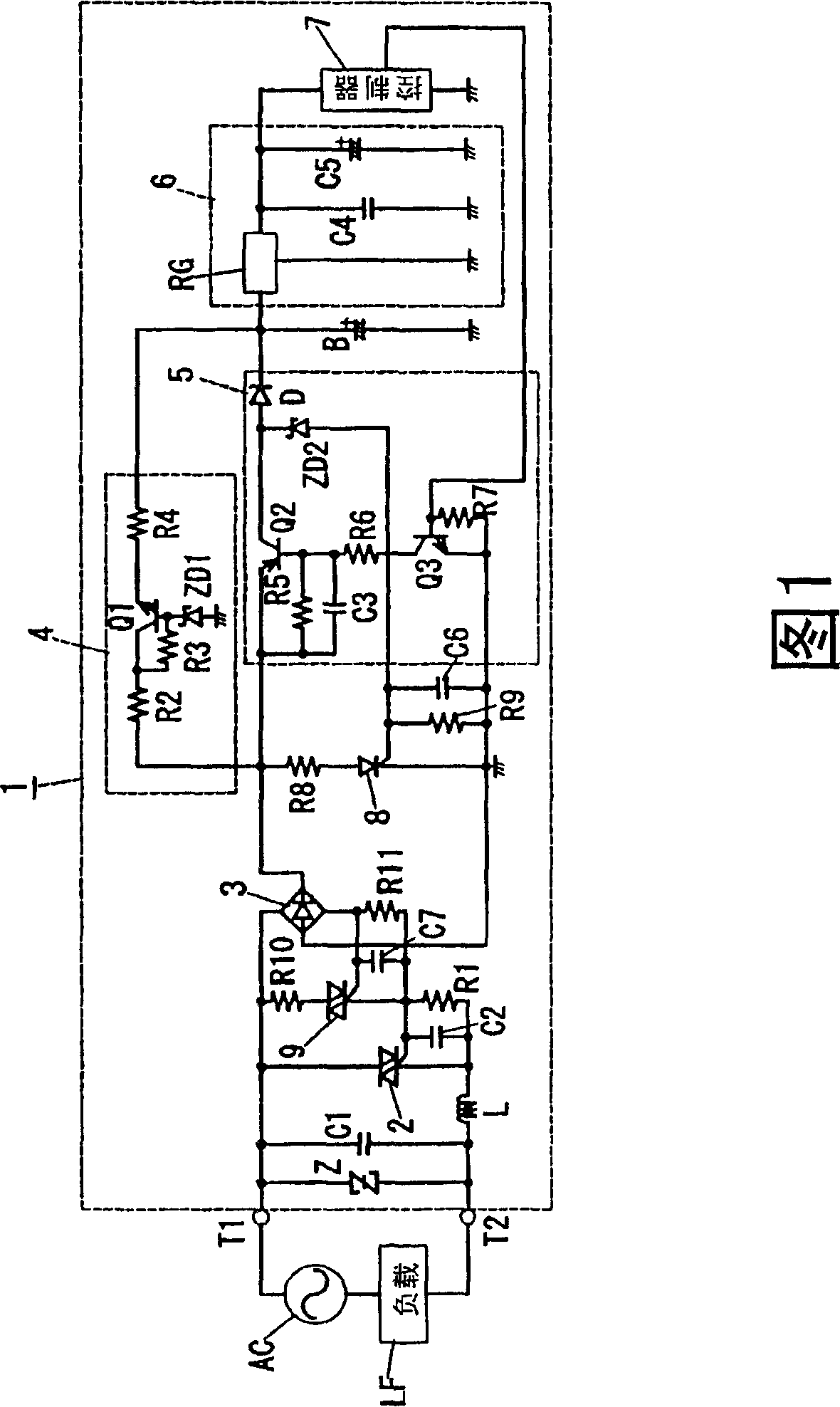
[0064] The two-wire switchgear 1 according to the first embodiment of the present invention is similar to the two-wire switchgear 100 shown in FIG. The installed switch box extends the two house wires from the commercial power supply to the commercial power supply and the load.
[0065] As shown in Fig. 1, the two-wire switching device 1 includes: a main switching unit 2 composed of a triac, wherein a load LF and an AC power supply are connected between two ends of the main switching unit 2 such that one end of the main switching unit 2 Connect to load LF via AC power supply AC; one end of the AC power supply AC). Here, the rectification unit 3 is used to apply a gate voltage to the gate terminal of the main switching unit 2 when the output terminal (DC output terminal) of the rectification unit 3 is short-circuited.
[0066] In addition, the two-wire switching device 1 also includes: a first power supply unit 4, used to generate DC power based on the output of the rectifier...
no. 2 example
[0091] As shown in FIG. 4 , the two-wire switching device 10 according to the second embodiment of the present invention has the same structure as the first embodiment except that a smoothing capacitor C8 is connected between the DC output terminals of the rectifying unit 3 . Since parts of the two-wire switching device 10 other than the smoothing capacitor C8 are the same as those of the first embodiment, the same parts will be denoted by the same reference numerals, and description thereof will be omitted.
[0092] According to the two-wire switching device 10 of the second embodiment, the same performance as that of the first embodiment is obtained, and in addition, the output of the rectifying unit 3 is smoothed by the smoothing capacitor C8. Therefore, sudden changes in the switching voltage when the DC output terminals of the rectifying unit 3 are short-circuited can be mitigated, thereby achieving further noise reduction.
no. 3 example
[0094] As shown in FIG. 5 , the structure of the two-wire switching device 11 according to the third embodiment of the present invention differs from that of the first embodiment mainly in that a sub switching unit 80 is provided instead of the sub switching unit 8 . Since most of the two-wire switching device 11 is configured the same as the first embodiment except for the sub-switch unit 80, the same parts will be denoted by the same reference numerals, and description thereof will be omitted.
[0095] Compared with the two-wire switch unit 1 of the first embodiment provided with the sub-switch unit 8 composed of a triac, the two-wire switch unit 11 of the present embodiment is provided with a sub-switch composed of a field effect transistor (FET). Unit 80.
[0096]Furthermore, in the two-wire switching unit 1 of the first embodiment, the anode of the Zener diode ZD2 is connected to the gate terminal of the sub-switching unit 8, and the gate of the sub-switching unit 8 is dr...
PUM
 Abstract
Description
Claims
Application Information