Frequency modulation system circuit

A circuit and antenna circuit technology, applied in transmission systems, electrical components, etc., can solve the problems of difficult to achieve the distance between the antenna and the motherboard, large internal space, etc.

Inactive Publication Date: 2008-04-23
INVENTEC(NANJING) TECH CO LTD
View PDF0 Cites 6 Cited by
  • Summary
  • Abstract
  • Description
  • Claims
  • Application Information

AI Technical Summary

Problems solved by technology

However, the former requires a large internal space, and the latter is difficult to achieve due to the spacing between the antenna and the ground of the motherboard

Method used


Image

  • Frequency modulation system circuit
  • Frequency modulation system circuit
  • Frequency modulation system circuit

Examples


Embodiment Construction

[0018] The invention provides a circuit design of a frequency modulation system, especially for use in a frequency modulation (FM) receiving antenna. Adding a low noise amplifier to the antenna circuit can improve the receiving sensitivity of the antenna, compensate for the loss of the antenna, and reduce the size of the antenna. , to achieve the purpose of building the FM antenna into the electronic device.

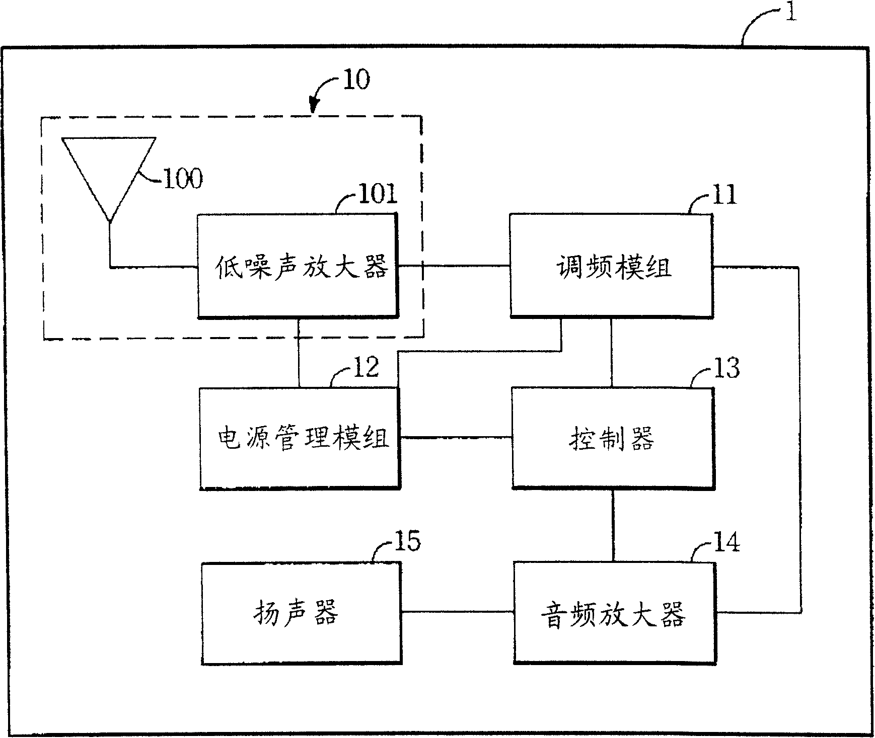
[0019] Please refer to figure 1 As shown, it is a structural schematic diagram of a frequency modulation system circuit according to an embodiment of the present invention. The frequency modulation (FM) system circuit 1 includes a frequency modulation (FM) antenna circuit 10, a frequency modulation module (FM module) 11, a power management module 12, a controller 13, an audio amplifier (Audio Amplifier) ​​14 and a speaker (Speaker) 15. Wherein, the FM antenna circuit 10 includes a (built-in) antenna 100, a frequency modulation low noise amplifier (FM-LNA) and its match...


PUM


Abstract

This invention discloses an FM system circuit including: an antenna circuit with an antenna, a low noise amplifier and a matching circuit, a support structure and a feed line for receiving signals, an FM module connecting to the antenna circuit for processing the FM signals and converting them to audio signals and a controller connected to the FM module for configuring and outputting audio signals, in which, the size of the antenna circuit can be reduced for being placed in an electronic device since the low noise amplifier and the matching circuit improve receiving of the antenna circuit.

Description

technical field [0001] The invention relates to a frequency modulation system circuit, in particular to a frequency modulation system circuit in which a low noise amplifier (Low Noise Amplifier, LNA) is added to improve the receiving sensitivity of a frequency modulation antenna. Background technique [0002] In recent years, the rapid development of the communication industry, due to the rapid development of the basic semiconductor industry and digital signal processing (Digital Signal Processing, DSP) technology, thus driving the progress of the communication industry. Among the three emerging areas of the communications industry, mobile communications, satellite communications, and optical fiber communications, mobile communications are most closely related to individuals. With the rapid development of the communication industry, the demand for antennas used in the wireless communication industry is also becoming increasingly diverse. With the trend of products becoming ...

Claims


Application Information

Patent Timeline
Patent Type & Authority Applications(China)
IPC IPC(8): H04B1/16
Inventor 袁小六高松陈浩
Owner INVENTEC(NANJING) TECH CO LTD
Why Eureka
Try Eureka