
Heat pipe residual heat recovery type drying machine

A waste heat recovery and drying machine technology, applied in the direction of dryers, drying, heating devices, etc., can solve the problems of energy waste, environmental heat pollution, etc., and achieve the effect of saving space

Inactive Publication Date: 2008-04-30
JIANGSU MUYANG GRP CO LTD
View PDF0 Cites 7 Cited by
  • Summary
  • Abstract
  • Description
  • Claims
  • Application Information

AI Technical Summary

Problems solved by technology

A large amount of high-temperature humid gas is discharged into the atmosphere in vain. Although some gas recycling methods are used to reduce this loss, a lot of energy is still wasted in the operation of the equipment. At the same time, there are still thermal pollution of the environment

Method used


Image

  • Heat pipe residual heat recovery type drying machine
  • Heat pipe residual heat recovery type drying machine

Examples


Embodiment Construction

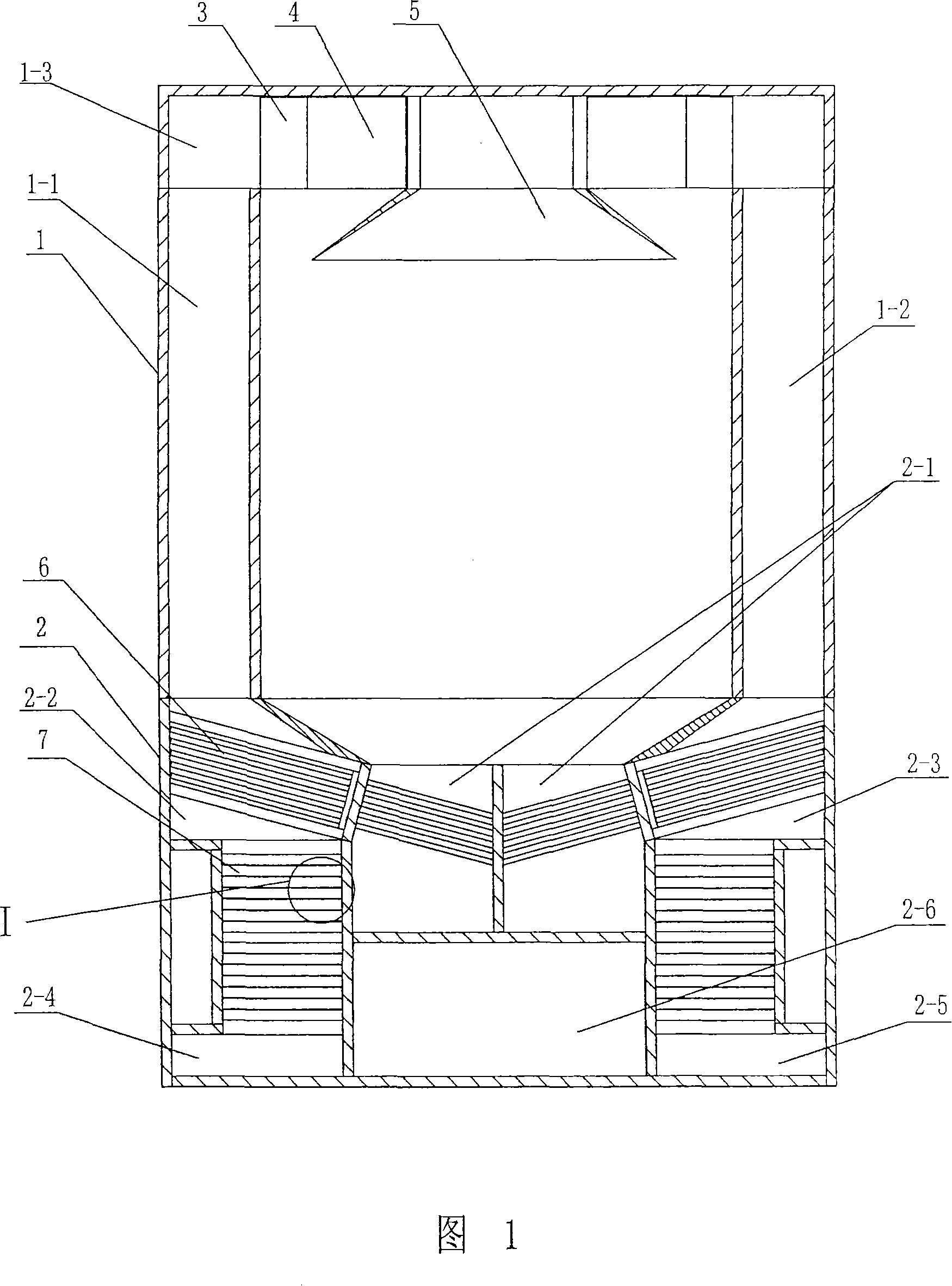
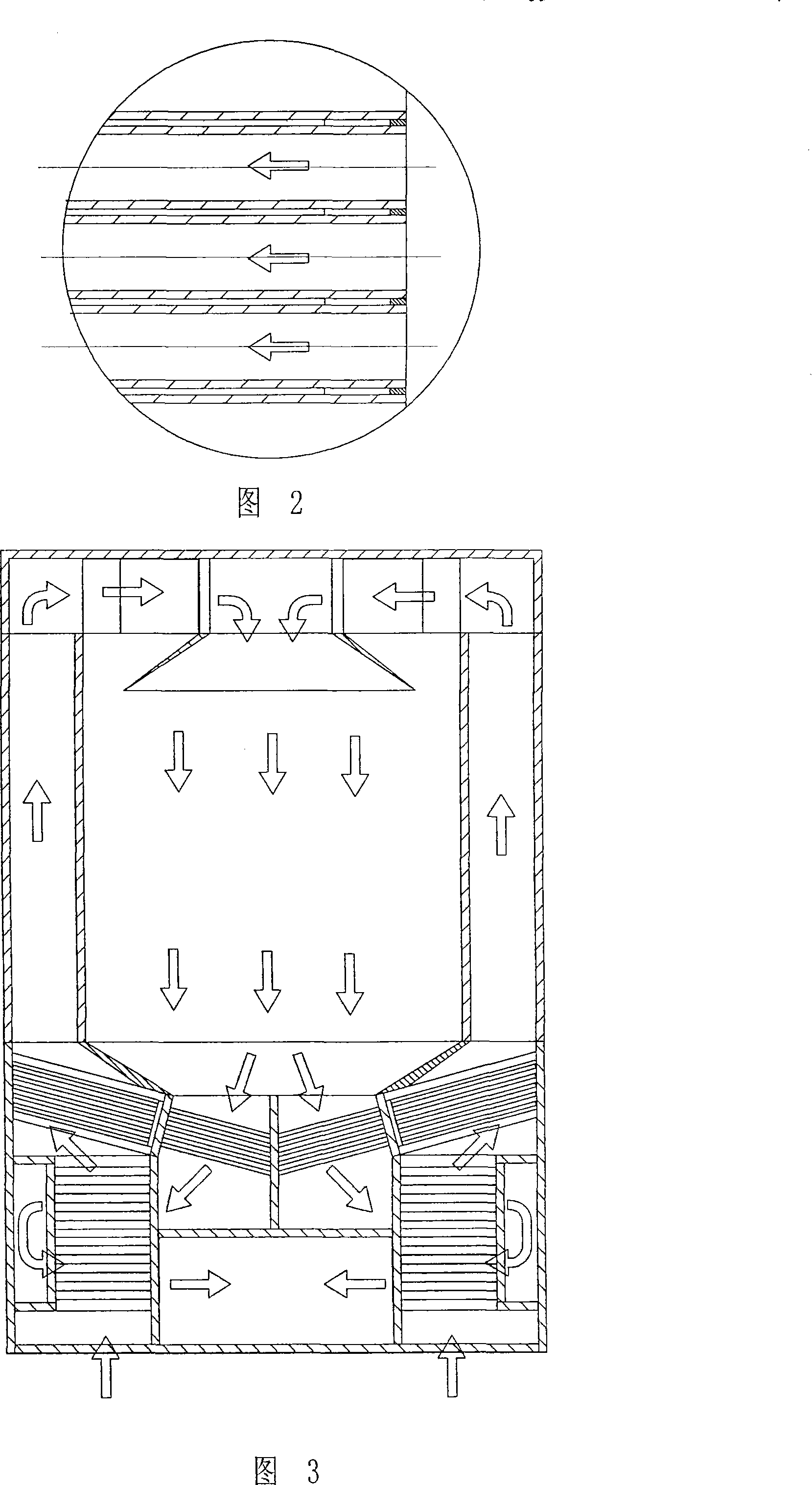
[0013] As shown in Figures 1, 2 and 3, the present invention is provided with drying box 1 and auxiliary box 2 two major parts.

[0014] The drying box 1 is provided with a left interlayer 1-1, a right interlayer 1-1 and an upper interlayer 1-3, the bottom is connected with the upper end of the auxiliary box body 2, and the two ends of the drying box 1 are provided with open material inlets and outlets.

[0015] In the upper interlayer 1-3 of the drying box 1, a steam heater 4 and a condensed water heater 3 are arranged symmetrically along the center, and an air flow distributor 5 is arranged in the upper center of the drying box 1. The air inlet of the air distributor 5 communicates with the shell-side outlet of the steam heater 4, and the shell-side inlet of the condensate heater 3 communicates with the upper ends of the left and right 1-1 and 1-2 interlayers respectively through the upper interlayer 1-3 , the shell side outlet of condensate heater 3 is connected with the sh...


PUM


Abstract

The invention relates to a hot tube afterheat reclaiming drier and relates to the technical field of drying device. The lower part of a drying box is connected with an auxiliary box body inside of which is provided with a middle channel and the channels on the two sides, the middle channel is communicated with the bottom of the drying box, while the upper ends of the channels on the two sides are respectively communicated with the bottoms of the left interlayer and the right interlayer of the drying box, the channels on the two sides are communicated with the lower part of the middle channel; the inside of the auxiliary box body is distributed with a heat exchanging tube two ends of which are enclosed, a part of the heat exchanging tube is distributed in the middle channel while the other part is distributed in the channels on the two sides. The heat contained in the damp gas permuted in the material reaches the auxiliary box body though the bottom of the drying box, the heat exchanger is utilized to distill heat from the damp gas, and the heat is simultaneously used for preheating the drying medium so as to further reach that the energy can be logically utilized during the whole drying craftwork process with biggest of the heat efficiency during the craftwork process, thereby reaching the purposes of energy saving and wastage reducing.

Description

technical field [0001] The invention relates to the technical field of drying equipment. Background technique [0002] Almost all dryers that use hot air or other hot gas as the medium for drying have the problem of low thermal energy utilization of the hot and humid gas. A large amount of high-temperature humid gas is discharged into the atmosphere in vain. Although some gas recycling methods are used to reduce this loss, a lot of energy is still wasted in the operation of the equipment. At the same time, there are still thermal pollution of the environment. Contents of the invention [0003] The purpose of the present invention is to design a heat pipe waste heat recovery dryer that can fully recover waste heat and reduce heat pollution. [0004] The invention comprises a drying box with material inlet and outlet at both ends, the drying box is provided with left, right and upper interlayers, a steam heater and a condensed water heater are arranged in the upper interla...

Claims


Application Information

Patent Timeline
Patent Type & Authority Applications(China)
IPC IPC(8): F26B23/10
CPCY02P70/10
Inventor 孙卫东孙旭清张文良车轩
Owner JIANGSU MUYANG GRP CO LTD
Learn More