Real-time timepiece chip interface circuit control method and real-time timepiece control circuit

A real-time clock and interface circuit technology, applied in the field of electronics, can solve the problems of reading the wrong time, heavy CPU burden, and heavy CPU burden, so as to reduce the pressure on the CPU, avoid read and write conflicts, and improve real-time performance.

Inactive Publication Date: 2008-04-30
WUXI POWER SUPPLY JIANGSU PROVINCE ELECTRIC POWER
View PDF1 Cites 12 Cited by
  • Summary
  • Abstract
  • Description
  • Claims
  • Application Information

AI Technical Summary

Problems solved by technology

So if the time is frequently read, and the CPU has other important tasks to perform, the CPU will be overwhelmed; if there are some tasks with strong real-time requirements, the consequences will be disastrous
Another problem is: the CPU reading time is at the nanosecond level, and the access speed is very fast. It is very likely that the CPU reading occurs during the period when the data transmitted by the I2C bus has not been completed. At this time, it is very likely to read the wrong data. time
[0008] Patent No. 200420041374.X describes a real-time clock control circuit, but it has the danger of overloading the CPU and inaccurate time when doing frequent time reading operations
[0009] Therefore, in order to overcome the problem that the real-time clock in the prior art causes the CPU to be overloaded and make mistakes when it is frequently read, it is necessary to provide a control method for a real-time clock chip interface circuit with high integration and strong functions.

Method used


Image

  • Real-time timepiece chip interface circuit control method and real-time timepiece control circuit
  • Real-time timepiece chip interface circuit control method and real-time timepiece control circuit
  • Real-time timepiece chip interface circuit control method and real-time timepiece control circuit

Examples


Embodiment Construction

[0031] The preferred embodiments of the present invention will be described below in conjunction with the accompanying drawings. It should be understood that the preferred embodiments described here are only used to illustrate and explain the present invention, and are not intended to limit the present invention.

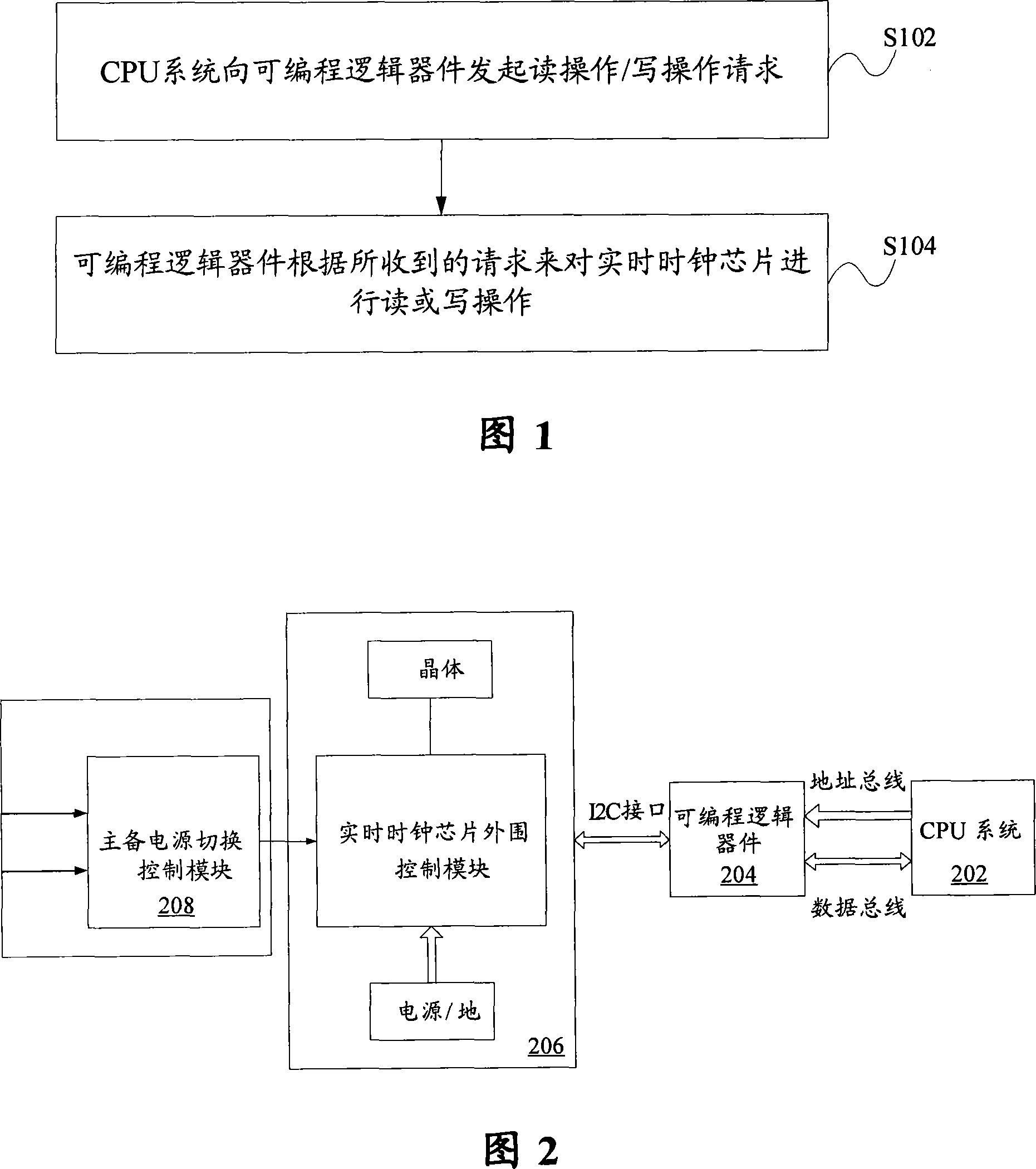
[0032] FIG. 1 is a flowchart showing a control method of a real-time clock chip interface circuit according to an embodiment of the present invention. As shown in Figure 1, the control method includes the following steps:

[0033] Step S102, the CPU system initiates a read operation / write operation request to the programmable logic device; and

[0034] Step S104, the programmable logic device reads or writes the real-time clock chip according to the received request.

[0035] When the CPU system initiates a write operation request to the programmable logic device, the following processing is performed in step S104: the CPU system writes the data to be written into ...


PUM


Abstract

The invention discloses a control method for a real-time clock chip interface circuit, a real-time clock circuit and a programmable logical circuit for the control of the real-time clock chip, wherein, the control method for the real-time clock chip interface circuit comprises the following procedures: procedure S102, wherein, a CPU system sends out the requests of reading / writing operation to a programmable logical device; and procedure S104, wherein, the programmable logical device performs reading or writing operation on the real-time clock chip according to requests received. Therefore, the invention significantly reduces the stress of CPU and saves a huge amount of time through a hardware-realizing mode, thereby not only improving the real-time performance of processing but also avoiding reading-writing conflicts.

Description

technical field [0001] The invention relates to the field of electronic technology, and more specifically, to a control method of a real-time clock chip interface circuit, a real-time clock control circuit, and a programmable logic circuit for controlling the real-time clock chip. Background technique [0002] In the field of electronic application design, the design of a real-time clock is required in many occasions as a time-based record or reference time for alarms or performance statistics, and its performance directly affects the quality of the entire system. A real-time clock often needs to meet the following conditions: [0003] First, accurate online timing; [0004] Second, more accurate timing can still be maintained within a period of time when the power is cut off; [0005] Third, during the network operation, the operation of frequently reading the time will not cause too heavy load on the system. [0006] The usual practice in the art is to use the I2C inter...

Claims


Application Information

Patent Timeline
Patent Type & Authority Applications(China)
IPC IPC(8): G06F1/14
Inventor 郭向东
Owner WUXI POWER SUPPLY JIANGSU PROVINCE ELECTRIC POWER
Why Eureka
Try Eureka