Pre-pressure device of magnetic force pressure enforcement and micro bending ultrasonic electromotor based on this device

An ultrasonic motor and pre-pressure technology, applied in piezoelectric effect/electrostrictive or magnetostrictive motors, generators/motors, electrical components, etc., can solve the problem of large radial size, thick axial size, pre-pressure Complicated device structure and other problems, to achieve the effect of small radial dimension, short axial dimension and easy external dimension

Inactive Publication Date: 2008-04-30
HARBIN INST OF TECH
View PDF2 Cites 5 Cited by
  • Summary
  • Abstract
  • Description
  • Claims
  • Application Information

AI Technical Summary

Problems solved by technology

[0003] The invention solves the shortcomings of the existing ultrasonic motors, such as large radial size, thick axial size, and complex structure of the pre-pressure device, and proposes a pre-pressure device for magnetic pressure and a miniature bending ultrasonic motor using the device

Method used


Image

  • Pre-pressure device of magnetic force pressure enforcement and micro bending ultrasonic electromotor based on this device
  • Pre-pressure device of magnetic force pressure enforcement and micro bending ultrasonic electromotor based on this device
  • Pre-pressure device of magnetic force pressure enforcement and micro bending ultrasonic electromotor based on this device

Examples


specific Embodiment approach 1

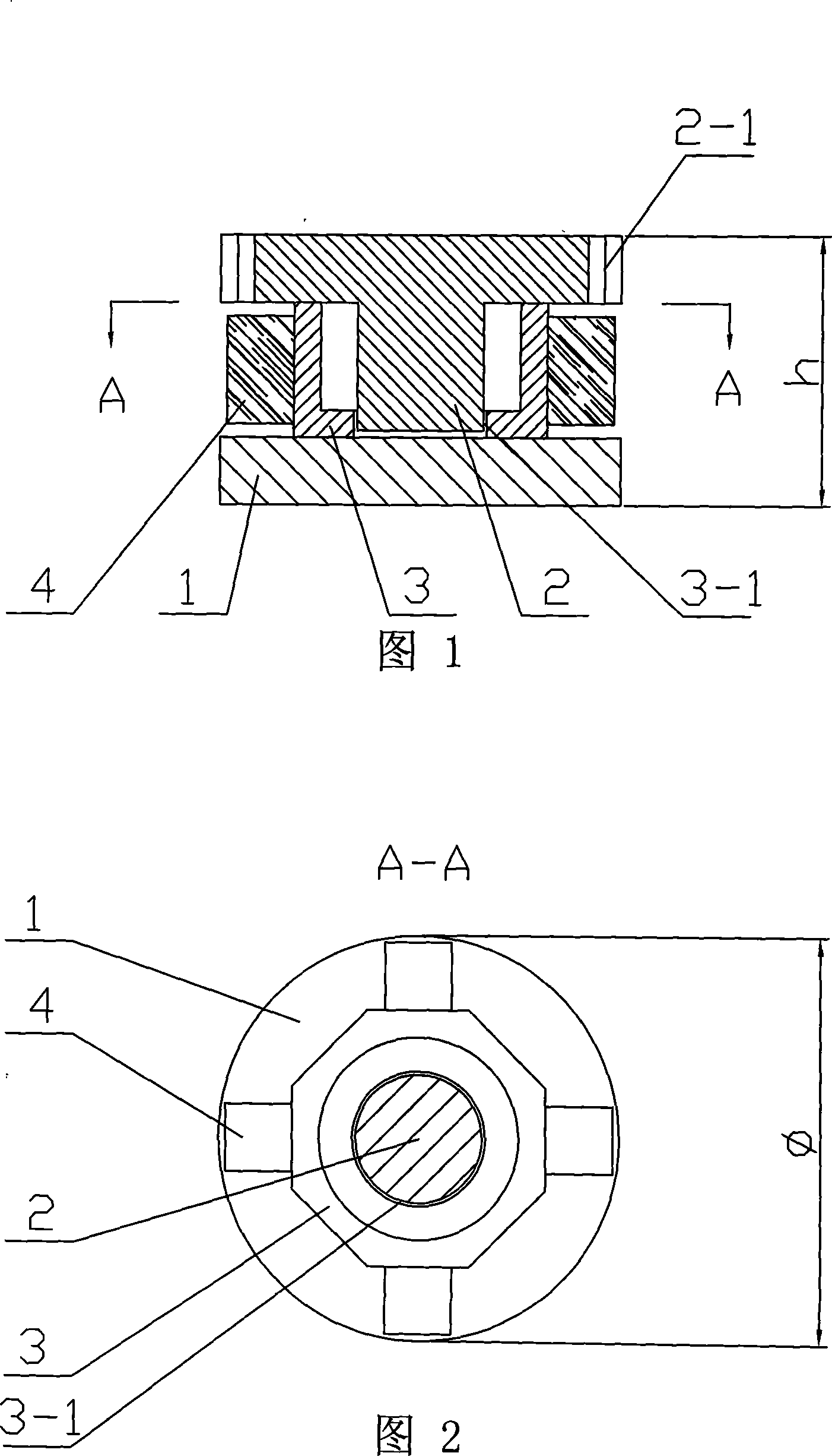
[0007] Specific Embodiment 1: This embodiment is described with reference to FIG. 1 and FIG. 2 . The magnetic pressure preloading device 1 of this embodiment adopts magnetic steel, and the magnetic steel is a circular sheet. The magnetic steel is a permanent magnetic material such as N35 or N42.

specific Embodiment approach 2

[0008] Embodiment 2: This embodiment is described with reference to FIG. 1 and FIG. 2 . The difference between this embodiment and Embodiment 1 lies in that the thickness of the disc-shaped magnetic steel is 0.1mm-1mm, and the outer diameter is 1mm-4mm.

specific Embodiment approach 3

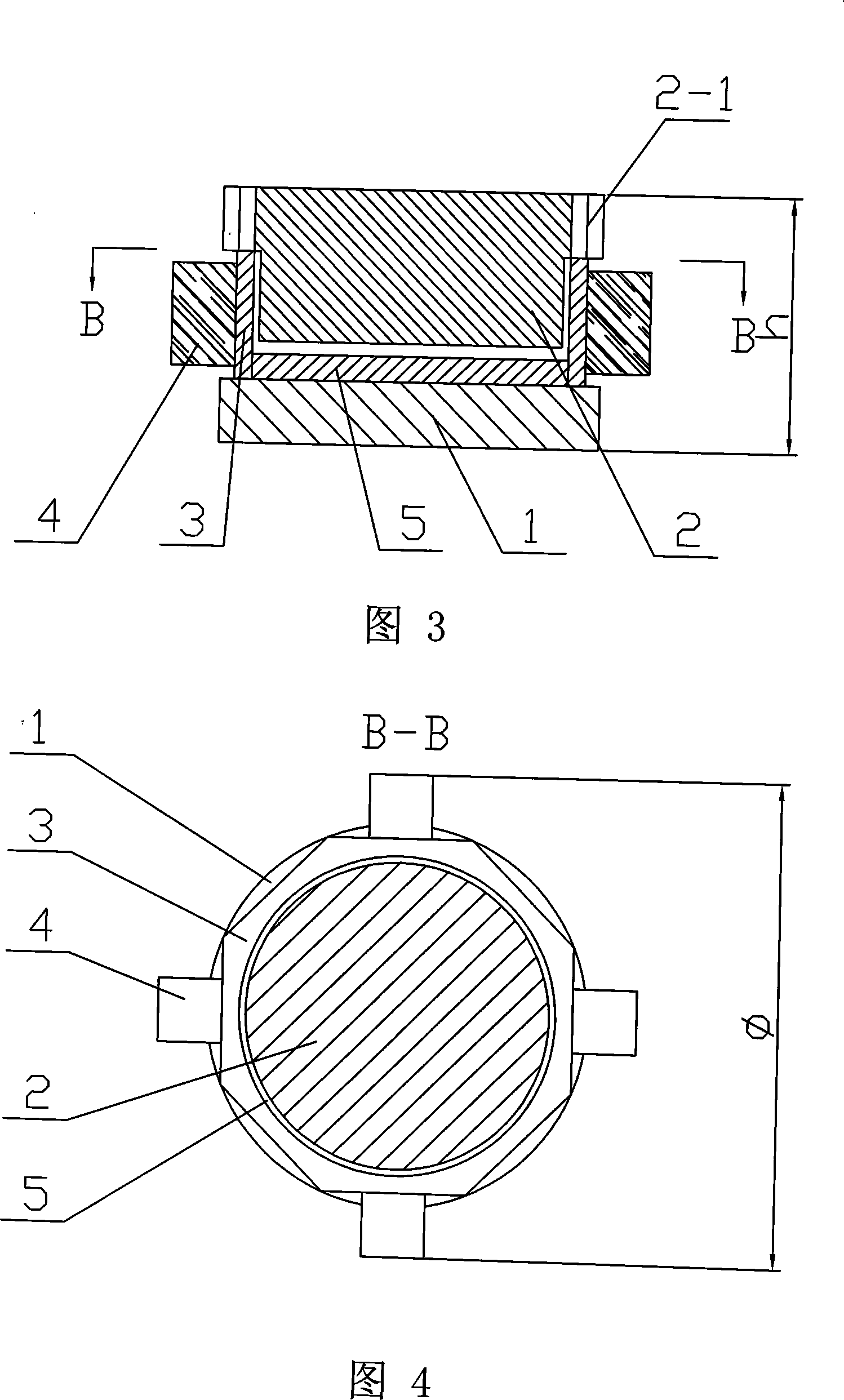
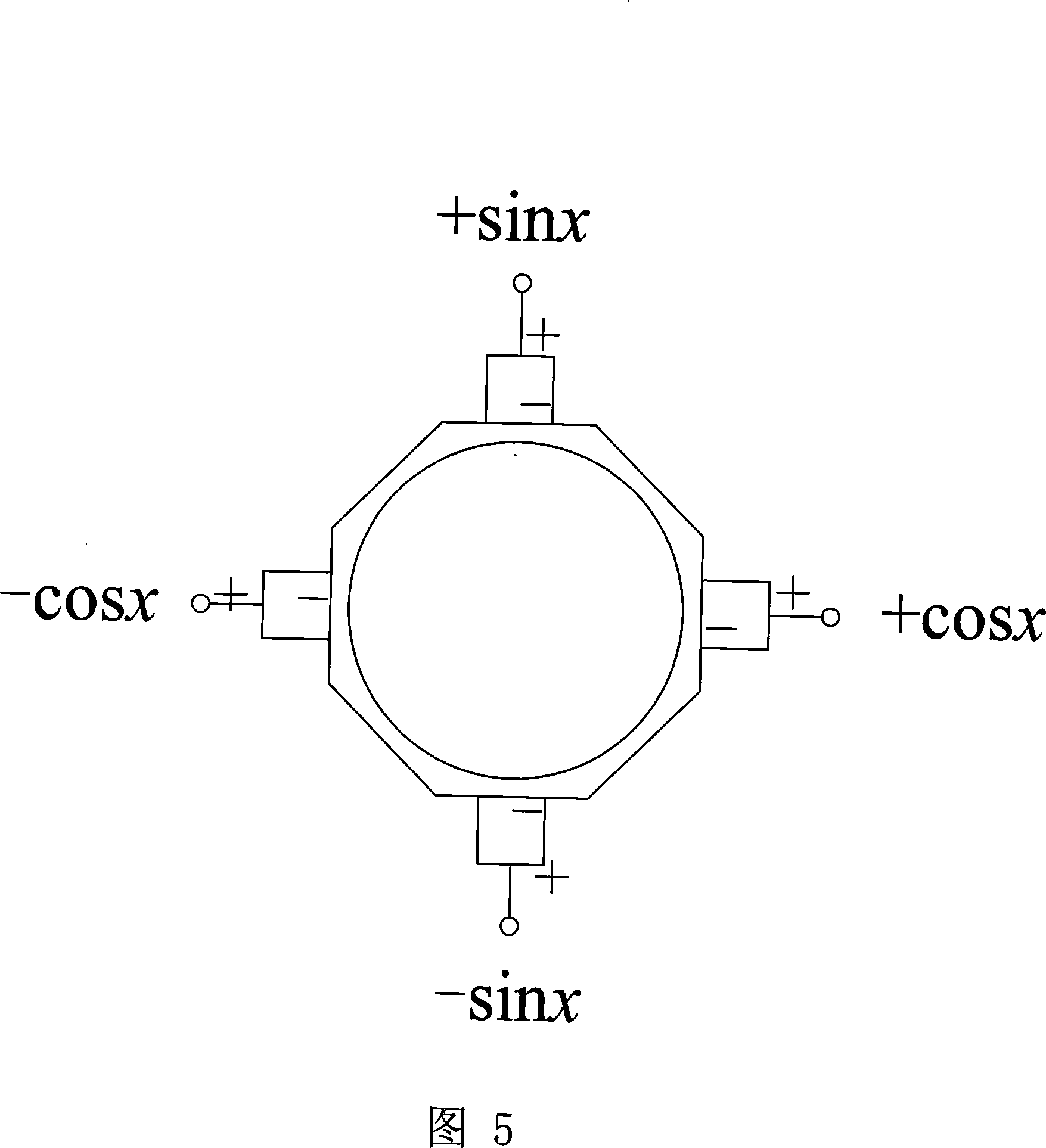
[0009] Specific Embodiment Three: This embodiment is described in conjunction with Fig. 1 , Fig. 2 , and Fig. 5. The micro-bending ultrasonic motor of this embodiment using a magnetically pressurized preload device is composed of a rotor 2, a stator, and a magnetically pressurized preload device 1 Composition; the magnetic pressure pre-pressure device 1 is fixed on the bottom of the stator; the stator is composed of a metal base 3 and four piezoelectric elements 4 of the same size, and the metal base 3 has a cylindrical cavity in the center The octagonal tube, the eight facets on the outer surface of the metal base 3 play a role in reducing the rigidity of the stator; the metal base 3 is made of a non-magnetic metal material, and a piece of piezoelectric element 4 is fixed on each edge of the metal base 3 . The electrical element 4 respectively applies traveling wave excitation signals of sine wave (sin(ωt)), cosine wave (cos(ωt)), negative sine wave (-sin(ωt)), and negative co...


PUM


Abstract

The invention discloses a pre-pressure device for magnetic pressure and a miniature bending ultrasonic motor using the device, which relates to the field of ultrasonic motors. The invention solves the shortcomings of the existing ultrasonic motors, which are large in radial direction, thick in axial direction and complex pre-pressure device. The pre-pressure device (1) of magnetic force pressurization of the present invention adopts the magnetic steel of circular sheet, and it is fixed on the bottom of stator; Stator metal matrix (3) is the octagonal tube that the center has cylindrical cavity, metal matrix (3) ) adopts a non-magnetic metal material, and a piece of piezoelectric element (4) is fixed on each edge of the metal base (3). The section of the rotor (2) is a "T"-shaped circular platform structure. The side wall of the body is provided with a gear (2-1), the rotor (2) is made of magnetically permeable material, and the lower platform of the rotor (2) is placed in the hollow cylindrical cavity of the stator metal base (3). The ultrasonic motor of the present invention has obvious advantages such as short axial direction, small radial direction, simple pre-pressure device, and convenient installation and fixing, and also has the characteristics of simple processing and low manufacturing cost.

Description

technical field [0001] The invention relates to the field of ultrasonic motors. Background technique [0002] Ultrasonic motor is a new type of direct drive motor that uses the inverse piezoelectric effect of piezoelectric ceramics to excite ultrasonic vibration, and through the friction drive between the stator and rotor, realizes the conversion of electrical energy into mechanical energy output. Among them, the bending and rotating ultrasonic motor is a kind of traveling wave ultrasonic motor. According to the shape of the stator and piezoelectric elements, it can be divided into piezoelectric tube and metal tube type, piezoelectric column and metal column type, and piezoelectric sheet sandwich type. Although there are many configurations of bending and rotating ultrasonic motors, the driving principle is basically the same. It excites the piezoelectric ceramic elements on the stator to make the stator generate two orthogonal standing wave vibrations bent along the axial ...

Claims


Application Information

Patent Timeline
Patent Type & Authority Applications(China)
IPC IPC(8): H02N2/12H02N2/14
Inventor 曲建俊程廷海周宁宁田秀
Owner HARBIN INST OF TECH
Why Eureka
Try Eureka