A solar device with parallel refraction lens

A solar device and refraction lens technology, which is applied to lenses, optics, photovoltaic modules, etc., can solve problems such as deterioration of working conditions and uneven light intensity on the surface of batteries, and achieve the effects of improving working conditions, simplifying tracking, and improving working conditions

Inactive Publication Date: 2008-04-30
施国庆
View PDF0 Cites 15 Cited by
  • Summary
  • Abstract
  • Description
  • Claims
  • Application Information

AI Technical Summary

Problems solved by technology

But the light collected by the existing glass concentrating lens and reflective concentrating device forms a focal line or focus on the focal plane, which is suitable for solar energy utilization devices with tubular or spherical light-receiving surfaces, but it is not suitable for the current scale production. For flat monocrystalline silicon photovoltaic cells, the working conditions are greatly deteriorated due to the uneven light intensity on the surface of the cell.

Method used


Image

  • A solar device with parallel refraction lens

Examples


Embodiment Construction

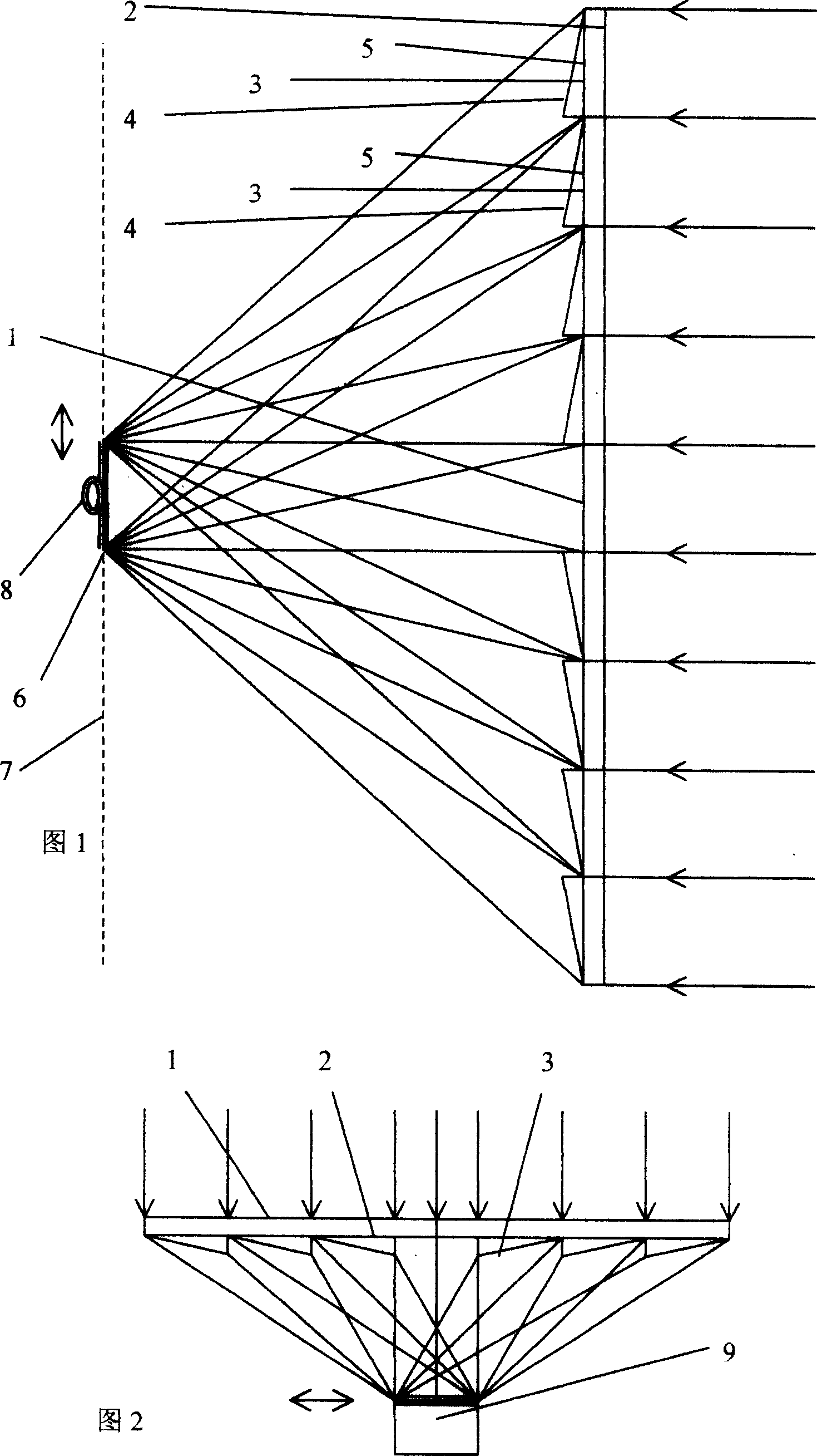
[0009] Figure 1 shows an embodiment of the present invention, a solar device with a one-dimensional parallel refractive lens. In the figure, a one-dimensional parallel dioptric lens 1 is composed of a plurality of refraction lens optics 3 arranged in a zigzag shape with flat refraction surfaces arranged on a glass plate 2 . Refractive lens optics 3 have two non-parallel planes—oblique refraction surface 4 and flat refraction surface 5 . Because it has two plane refraction surfaces, it is different from the situation that the common focusing convex lens has a focus. In the figure, the light emitted from the refraction lens 1 has refraction but no focus, and its projection area on the photocell 6 is still a light band. . The included angles between the two refraction surfaces of the adjacent refraction lens optics 3 are different, so that the projection areas of the refracted light of all the refraction lens optics 3 on the converging plane 7 can be accurately overlapped and ov...


PUM


Abstract

A solar energy device with parallel dioptric lens: parallel rays are emitted through a dioptric lens before overlapping and projecting in an area on a focusing plane, but no focus is formed. Compared with convex lenses, the maximum temperature of the invented focusing and photoelectric cell while working can be lowered by nearly one hundred centigrades in the same ratio; therefore, the power generation efficiency is rather high. Besides, two actual examples are also provided including a solar energy device with a one-dimensional parallel dioptric lens. The dioptric lens 1 comprises a plurality of saw-tooth shaped dioptric lenses 3 on a glass plate 2. The dioptric lenses 3 are composed of an inclined plane of refraction 4 and an horizontal plane of refraction 5. The rays emitted through the dioptric lens include refraction, but no focus, and the projection formed on the photoelectric cell 6 is a beam. Sun-light is focused through the one-dimensional dioptric lens 1 on the photoelectric cell 6 before being converted into electric energy and thermal energy. The electric energy is output through cables; the thermal energy is exchanged through a heat exchanger 8 for transmission. When the incident angle of sun-light is changed, the photoelectric cell 6 can also move vertically while tracing the light in a focusing plane 7.

Description

technical field [0001] The invention relates to a solar device with a parallel refraction lens. Background technique [0002] Concentrated solar power can reduce the amount of photovoltaic cells, improve efficiency and reduce costs. But the light collected by the existing glass concentrating lens and reflective concentrating device forms a focal line or focal point on the focal plane, which is suitable for solar energy utilization devices with tubular or spherical light-receiving surfaces, but for the current scale production For flat monocrystalline silicon photovoltaic cells, the working conditions are greatly deteriorated due to the uneven light intensity on the surface of the cell. Contents of the invention [0003] One of the objectives of the present invention is to provide a solar device with a parallel refraction lens. [0004] The object of the present invention is achieved like this: a solar device with a parallel refraction lens is formed with a parallel refra...

Claims


Application Information

Patent Timeline
Patent Type & Authority Applications(China)
IPC IPC(8): H02N6/00H02N11/00G02B3/02G02B3/08G02C7/02H02S10/00
CPCY02E10/50
Inventor 施国梁
Owner 施国庆
Why Eureka
Try Eureka