An encoding device with signal real time monitoring function
An encoding device and real-time monitoring technology, which is applied in digital video signal modification, pulse modulation TV signal transmission, image communication, etc., can solve the problems of increasing the complexity of system equipment, adding monitoring equipment, and the inconvenience of encoder monitoring. Equipment complexity, reduce use cost, achieve convenient effect
- Summary
- Abstract
- Description
- Claims
- Application Information
AI Technical Summary
Problems solved by technology
Method used
Image
Examples
Embodiment 1
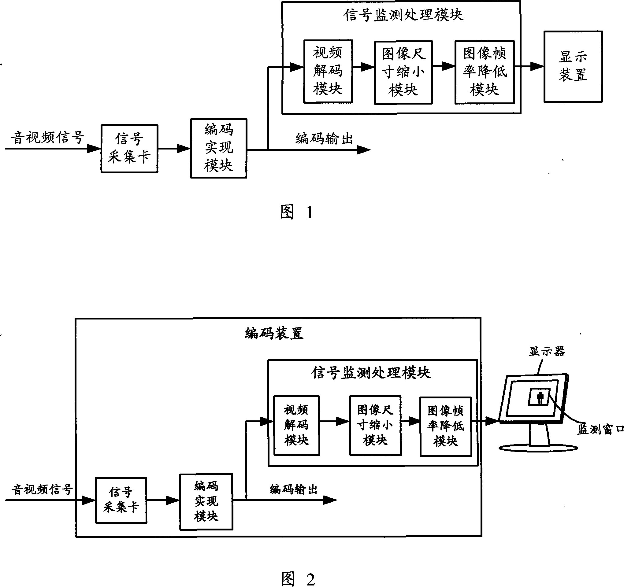
[0018] The video decoding module decodes the code stream output by the encoding implementation module into a digital YUV signal and sends it to the image size reduction module; the image size reduction module removes 8 pixels from the left and right sides of the original 720×576 large-scale image in the width direction, and then Take 4:1 equal interval down-sampling, directly perform 4:1 equal interval down-sampling in the height direction, reduce it into a small-sized image of 176×144, and transmit the signal to the image frame rate reduction module; the image frame rate reduction module converts the 25fps ( PAL system) high frame rate image, through the equal interval extraction of two frames to keep one frame and reduce it to 9fps low frame rate image, and then output to the display.
Embodiment 2
[0020] The video decoding module decodes the code stream output by the encoding implementation module into a digital YUV signal and sends it to the image frame rate reduction module; the image frame rate reduction module saves a frame with a high frame rate of 29.97fps (NTSC) by two frames at intervals The equal interval extraction reduces the image to 10fps low frame rate, and transmits the signal to the image size reduction module; the image size reduction module converts the original 720×480 large-size image, the width direction and the height direction respectively through 8:1 equal intervals The sampling method is reduced to a small size image of 90×60, and then output to the display.
[0021] The code stream output by the encoding realization module can be displayed in real time on the monitoring window of the display after being processed by the signal monitoring and processing module, so that it is convenient to detect whether the encoder is working normally.
PUM
 Abstract
Description
Claims
Application Information
 - R&D
- Intellectual Property
- Life Sciences
- Materials
- Tech Scout
- Unparalleled Data Quality
- Higher Quality Content
- 60% Fewer Hallucinations
Browse by: Latest US Patents, China's latest patents, Technical Efficacy Thesaurus, Application Domain, Technology Topic, Popular Technical Reports.
© 2025 PatSnap. All rights reserved.Legal|Privacy policy|Modern Slavery Act Transparency Statement|Sitemap|About US| Contact US: help@patsnap.com

