Control method and device for impact screw tightening device
一种紧固装置、控制方法的技术,应用在螺丝刀、制造工具、金属加工等方向,能够解决紧固扭矩精确度变动、旁通阀油压调整麻烦、油压脉冲部发热大等问题
- Summary
- Abstract
- Description
- Claims
- Application Information
AI Technical Summary
Problems solved by technology
Method used
Image

Examples
no. 1 Embodiment approach
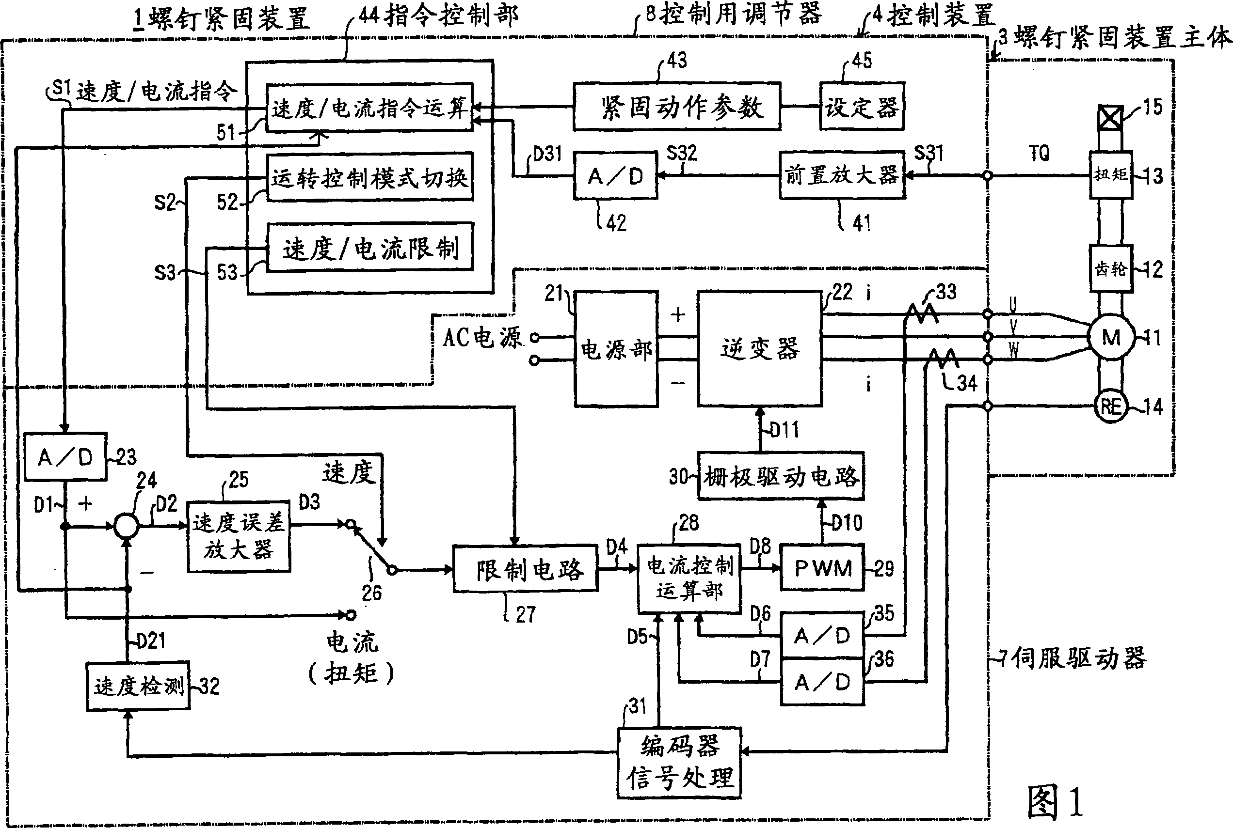
[0037] FIG. 1 is a block diagram showing the overall configuration of a screw fastening device 1 according to a first embodiment of the present invention.
[0038] In FIG. 1 , a screw fastening device 1 is composed of a screw fastening device main body 3 and a control device 4 having a servo driver 7 and a control regulator 8 .
[0039] The screw fastening device main body 3 is composed of a motor 11 , an impact generating device 12 , a torque sensor 13 , an encoder 14 , an output shaft 15 , an unillustrated case, a switch, and the like.
[0040] As the engine 11, for example, a three-phase AC servo motor is used. The impact generating device 12 is a collision energy generating mechanism that converts the rotational force of the engine 11 into intermittent impact force. Although various mechanisms are used as the impact generator 12, in this embodiment, reduction gears composed of planetary gears and the like are used. The backlash (clearance) of the planetary gears and the ...
no. 2 Embodiment approach
[0117] Next, a second embodiment of the present invention will be described.
[0118]In the first embodiment described above, the increase amount ΔI2 of the current pulse DP in the second stage is made smaller than the increase amount ΔI1 of the current pulse DP in the first stage. Therefore, after the tightening torque TQ reaches the target approaching torque TQN as the first set value, the increase amount ΔI2 of the current pulse DP is controlled so that the increase amount of each pulse of the tightening torque TQ is greater than that before reaching the target approaching torque TQN. smaller.
[0119] In contrast, in the second embodiment, when the tightening torque TQ reaches the target approaching torque TQN, the value of each pulse-shaped current supplied to the engine 11 is reduced. For other functions and structures, since there are many parts that are the same as those in the first embodiment, the description of the parts that are the same as those in the first embo...
no. 3 Embodiment approach
[0130] Next, a third embodiment of the present invention will be described.
[0131] Fig. 13 is a flowchart showing a torque secondary control processing routine according to the third embodiment of the present invention.
[0132] In the third embodiment, the first embodiment and the second embodiment are combined. That is, as shown in FIG. 13, in the first phase, the current value of the current pulse DP is set to D1T1 only for the first time (#61). Thereafter, when the tightening torque TQ has not reached the target approaching torque TQN (No in #62), an increment ΔI1 is added to the current value (#63). After the tightening torque TQ reaches the target approaching torque TQN (Yes in #62), set the current value of the current pulse DP to D1T2 (#64) only for the first time, and then add the increment ΔI2 to the current value (# 65). Also, the increase amount ΔI2 is a smaller value than the increase amount ΔI1.
[0133] That is, the third embodiment is a special case of th...
PUM
 Abstract
Description
Claims
Application Information
 - R&D
- Intellectual Property
- Life Sciences
- Materials
- Tech Scout
- Unparalleled Data Quality
- Higher Quality Content
- 60% Fewer Hallucinations
Browse by: Latest US Patents, China's latest patents, Technical Efficacy Thesaurus, Application Domain, Technology Topic, Popular Technical Reports.
© 2025 PatSnap. All rights reserved.Legal|Privacy policy|Modern Slavery Act Transparency Statement|Sitemap|About US| Contact US: help@patsnap.com