Diffractive optical component making method

A technology of diffractive optical elements and manufacturing methods, applied in optical elements, diffraction gratings, optics, etc., can solve problems such as the decline of diffraction efficiency, and achieve the effect of achieving diffraction efficiency

Inactive Publication Date: 2008-04-30
OKI ELECTRIC IND CO LTD
View PDF1 Cites 12 Cited by
  • Summary
  • Abstract
  • Description
  • Claims
  • Application Information

AI Technical Summary

Problems solved by technology

In this way, in the conventional manufacturing method, a stepped shape with a size different from the design value may be formed, or a protrusion may be generated at the edge, so there is a problem of causing a decrease in diffraction efficiency.

Method used


Image

  • Diffractive optical component making method
  • Diffractive optical component making method
  • Diffractive optical component making method

Examples


Embodiment Construction

[0043] Hereinafter, preferred embodiments of the present invention will be described in detail with reference to the drawings. In addition, in this specification and drawings, the same code|symbol is attached|subjected about the component which has substantially the same functional structure, and repeated description is abbreviate|omitted.

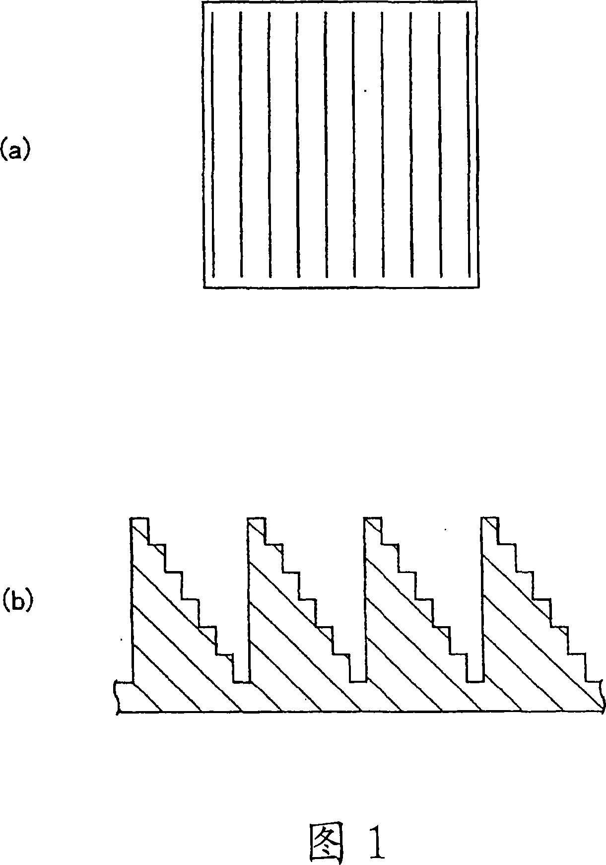
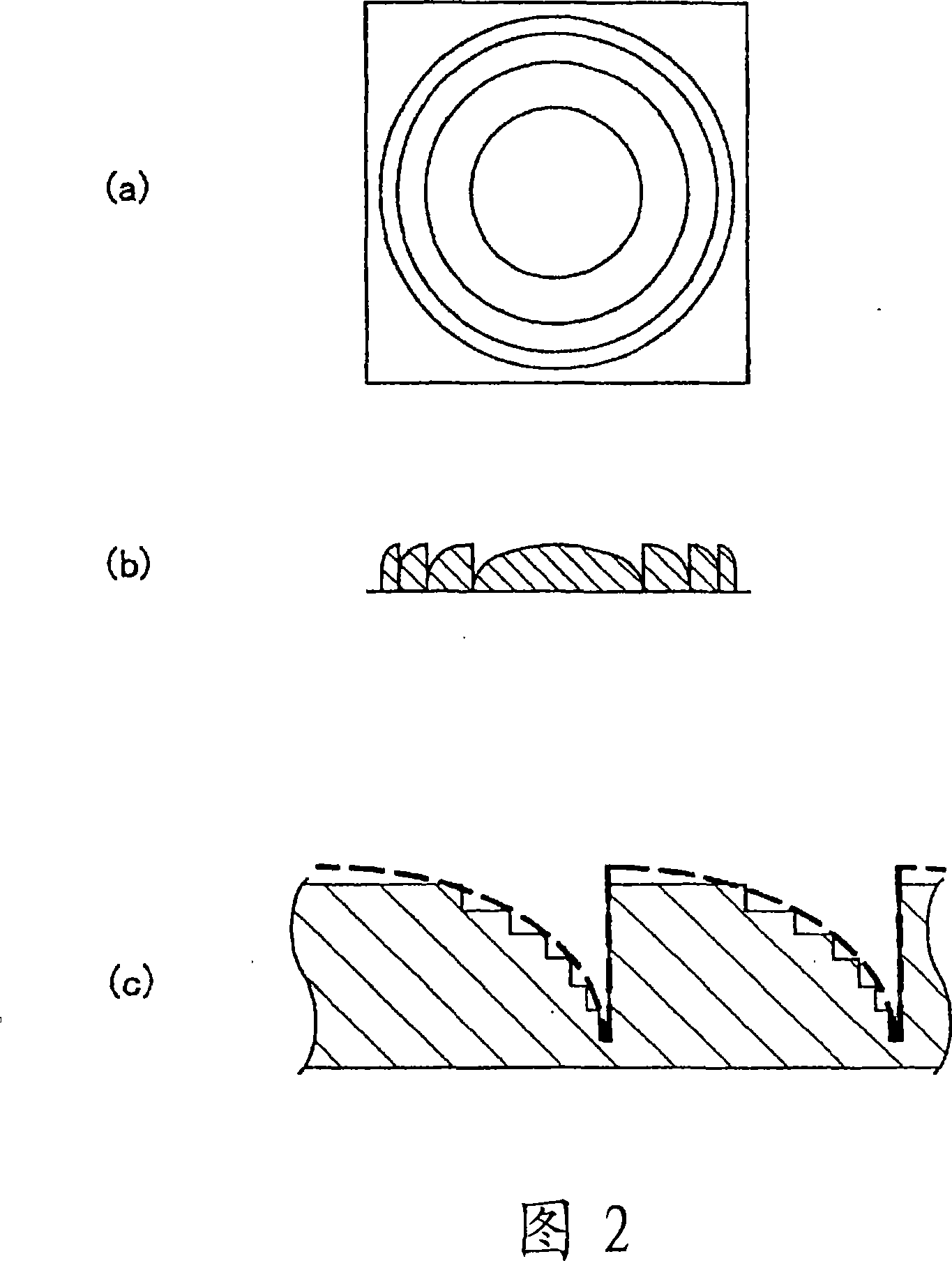
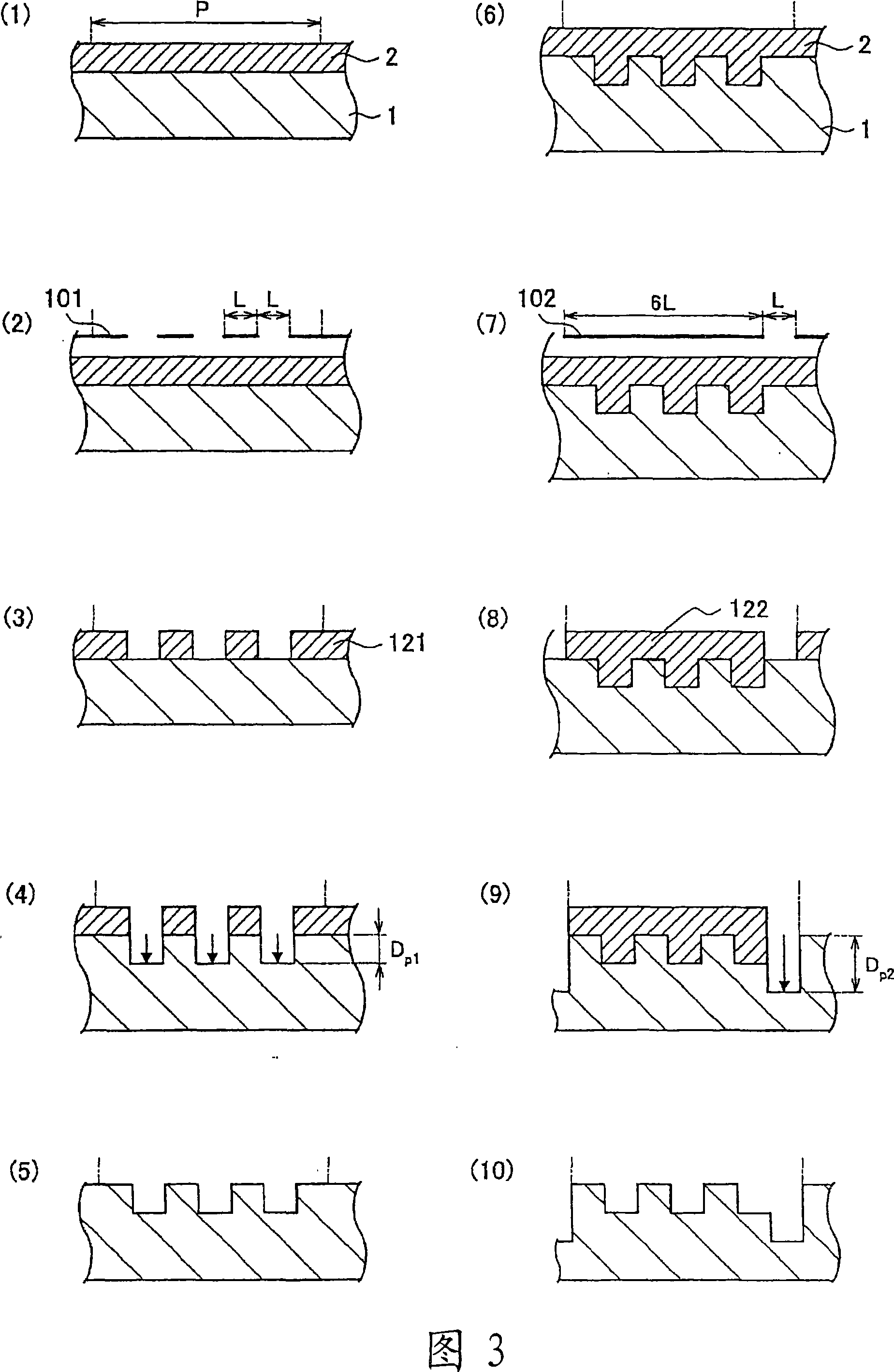
[0044] In the method of manufacturing a diffractive optical element according to an embodiment of the present invention, a diffractive optical element having a periodic stepped shape is manufactured by repeatedly performing a series of processes using semiconductor microfabrication technology. A series of processing refers to coating a resist on a substrate, exposing and developing the substrate using a mask formed with a predetermined pattern, and forming a resist consisting of a resist removed part and a resist remaining part. A resist pattern is used for etching.

[0045] In addition, there are various kinds of diffractive optical elem...


PUM


Abstract

To provide a method for fabricating a high precision diffraction optical element capable of enhancing diffraction efficiency. [MEANS FOR SOLVING PROBLEMS] A diffraction optical element having a periodical stepwise profile is fabricated by repeating a series of processes for exposing and developing a substrate (1) coated with resist (2) through a mask to form a resist pattern and then etching the resist pattern. In the first process, a pattern having a width identical to that of the step is formed and then the width of the pattern is increased in the subsequent processes. When fabricating a seven-step diffraction optical element assuming the level difference of step is D, the second, fourth and sixth step portions are etched with depth D in the first process the ninth step portion is etched with depth 2D in the second process, the fifth, sixth and seventh step portions are etched with depth 2D in the third process, and the third, fourth, fifth, sixth and seventh step portions are etched with depth 2D in the fourth process.

Description

technical field [0001] The present invention relates to a method of manufacturing a diffractive optical element having a stepped shape. Background technique [0002] In recent years, there has been an increasing demand for diffractive optical elements that control the traveling direction and phase of light based on periodic fine shapes. There are various shapes of diffractive optical elements. Among them, a diffractive optical element with a zigzag cross section has a high logical diffraction effect. In fact, a stepped diffractive optical element similar to the zigzag shape is easy to manufacture and is widely used. Generally, as a method of manufacturing a diffractive optical element having a stepped shape, there is a method described in the following Non-Patent Document 1, which uses m (m is a natural number) masks to repeatedly expose, A series of processes of developing and etching, manufacturing 2 m class diffractive optical elements. For example, in the case of an 8...

Claims


Application Information

Patent Timeline
Patent Type & Authority Applications(China)
IPC IPC(8): G02B5/18
CPCG02B5/1842G03F7/0035G02B5/1857
Inventor 关川亮前野仁典
Owner OKI ELECTRIC IND CO LTD
Why Eureka
Try Eureka