Layered quantitative gas filling device

A technology of steam injection and sub-injection valve, which is applied in the fields of production fluids, wellbore/well components, earth-moving drilling, etc., can solve the problems of oil well casing damage, unreasonable structure, lack of protection devices, etc. Effect

Inactive Publication Date: 2008-05-07
潘昌德
View PDF0 Cites 5 Cited by
  • Summary
  • Abstract
  • Description
  • Claims
  • Application Information

AI Technical Summary

Problems solved by technology

The layered and quantitative steam injection device used in the prior art can achieve better steam injection effect, but due to the unreasonable structure and lack of protection devices, the high-pressure steam flow is directly injected into the casing during steam injection, which will damage the oil well casing. The damage will not only bring difficulties to production, but also cause the oil well to be scrapped in serious cases. For this reason, a layered quantitative steam injection device for oil wells proposed by the present invention can protect the casing from damage and can stratify the heavy oil. Quantitative steam injection can greatly increase the production of heavy oil

Method used


Image

  • Layered quantitative gas filling device
  • Layered quantitative gas filling device

Examples


Embodiment 1

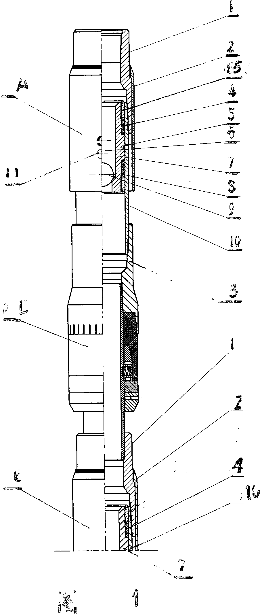
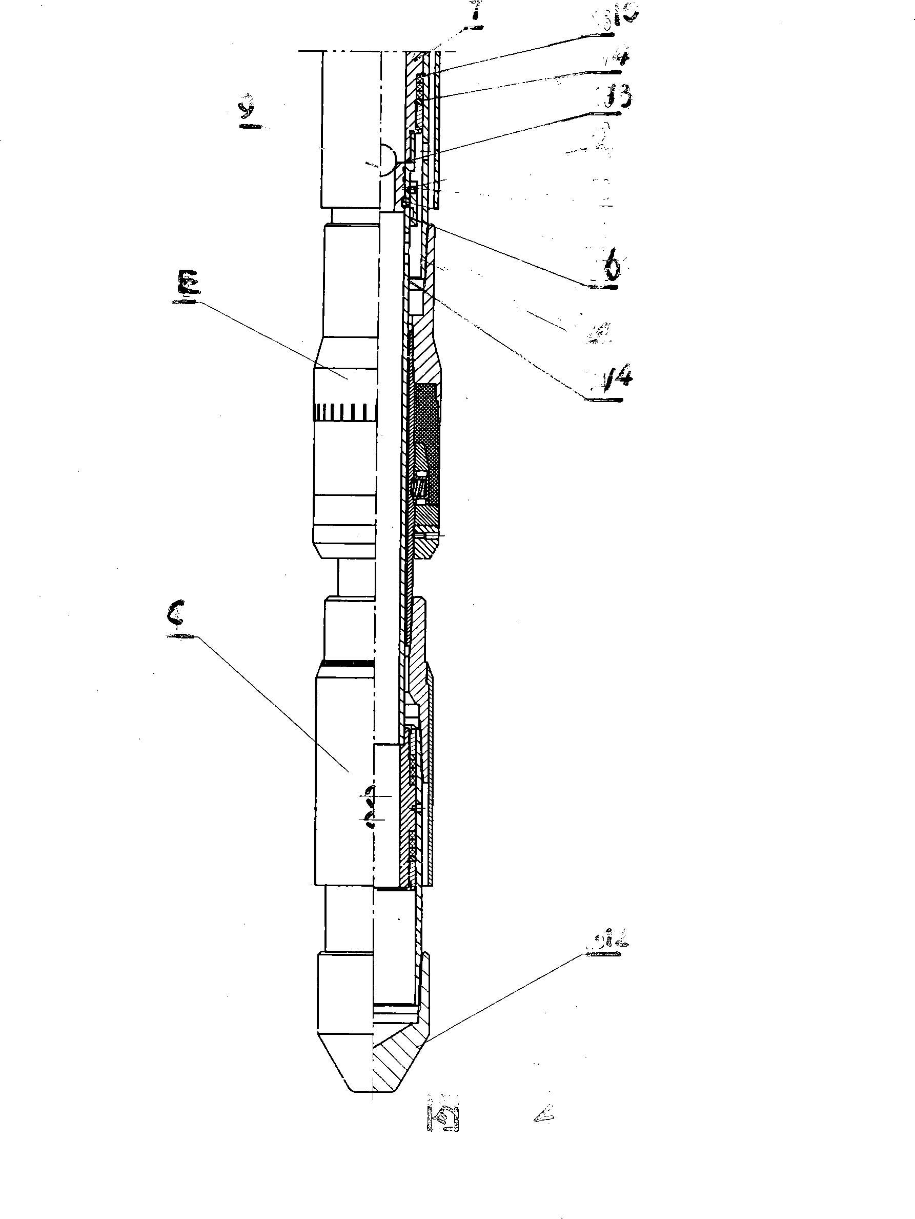
[0014] In Figures 1 and 2, the layered and quantitative steam injection device is connected between the lower end of the outer pipe 10 in the first-stage split injection valve A and the upward steam packer D through a variable diameter joint 3, and the upper steam seal The second-stage dispensing valve B and the third-stage dispensing valve C connected under the spacer are connected to the lower-injection steam packer E through the screw thread of the upper joint 1 and the reversing pipe.

[0015] The one-, two-, and three-stage dispensing valves are equipped with a pressure ring 15 and a graphite ring 4 on the upper joint 1 to seal the gap between the inner and outer tubes 10 and the inner tube 7 of the upper joint, and the inner tube 7 is installed inside the outer tube 10 , are fixed with shear pins 5 between each other, because there are air outlet holes 6 drilled on the inner pipe wall, and four air outlet holes are drilled on the outer pipe wall, so that when the steel ba...

Embodiment 2

[0018] When working, the upper joint 1 of the present invention is connected with the steam injection pipeline, and the lower end of the first-stage injection valve A is sequentially connected with the upper-injection steam packer D, the second-level injection valve B, and the lower-injection steam packer E , Three-stage separate injection valve C Finally screw the plug under the three-stage separate injection valve, that is, the assembly is completed. After the device goes down the well and enters the oil layer, it starts to inject high-temperature steam into the inner pipe 7 to seal the upper injection steam. The device D and the steam injection packer E are seated on the casing wall of the oil well, and then the steel ball 9 is put into the pipe string from the wellhead to press the upper and lower steam packers D and E. At this time, the shear The cutting pin 5 breaks, and the inner pipe 7 moves downward, so that the steam flows from the air outlet hole 6 of the inner pipe ...

Embodiment 3

[0019] Embodiment 3, the upward steam injection packer D and the downward steam injection packer E described in the present invention are thermal recovery steam injection packers in the prior art.


PUM


Abstract

The invention relates to a stratified quantitative steam injection device, belonging to a stratified steam injection device for thermal production well, comprising a primary separate injection valve connected with a secondary separate injection valve, a tertiary separate injection valve and a plug by upper joint screw. The primary separate injection valve and an upper packer are connected by a reducer union, the secondary separate injection valve and the tertiary separate injection valve, which are connected under an upper steam injection packer, are connected with a lower steam injection packer by an upper joint and an inverting pipe. When injecting steam, the direct impact on a bushing protector caused by high temperature steam can be avoided, due to the bushing protector arranged in the device, in addition, the device enables the quantitative steam injection for a heavy oil reservoir. The device has the advantages of simple structure, convenient use and wide application range in a stratified quantitative steam injection well of oil well.

Description

Technical field: [0001] The invention relates to a layered quantitative steam injection device, which belongs to the class of layered steam injection devices for thermal recovery wells of heavy oil. Background technique: [0002] The heterogeneity of heavy oil reservoirs and steam overlay and other factors will cause unbalanced production of oil layers in the well, so that the high degree of oil recovery in the high permeability layer, and the low degree of production in the middle and low permeability layers. If it is not used, it will affect the implementation of the overall development plan of the oilfield. In order to balance the production of oil reservoirs and improve the production degree of single well reservoirs and the whole layer, the current technology adopts the method of layered quantitative steam injection. This method can divide the oil layer into several units according to the physical properties of the oil layer and the degree of production of the oil well....

Claims


Application Information

Patent Timeline
Patent Type & Authority Applications(China)
IPC IPC(8): E21B43/24
Inventor 潘琳潘昌德宋福军万学文冯景杰沈英凯张岩李晓玲李长红刘海青王军高侃景宝国
Owner 潘昌德
Why Eureka
Try Eureka