State monitoring device for circuit breaker
A monitoring device and circuit breaker technology, which is applied to circuit devices, emergency protection circuit devices, and automatic disconnection emergency protection devices, etc., can solve problems such as damage to main contacts and achieve the effect of maintaining power supply.
- Summary
- Abstract
- Description
- Claims
- Application Information
AI Technical Summary
Problems solved by technology
Method used
Image
Examples
Embodiment approach 1
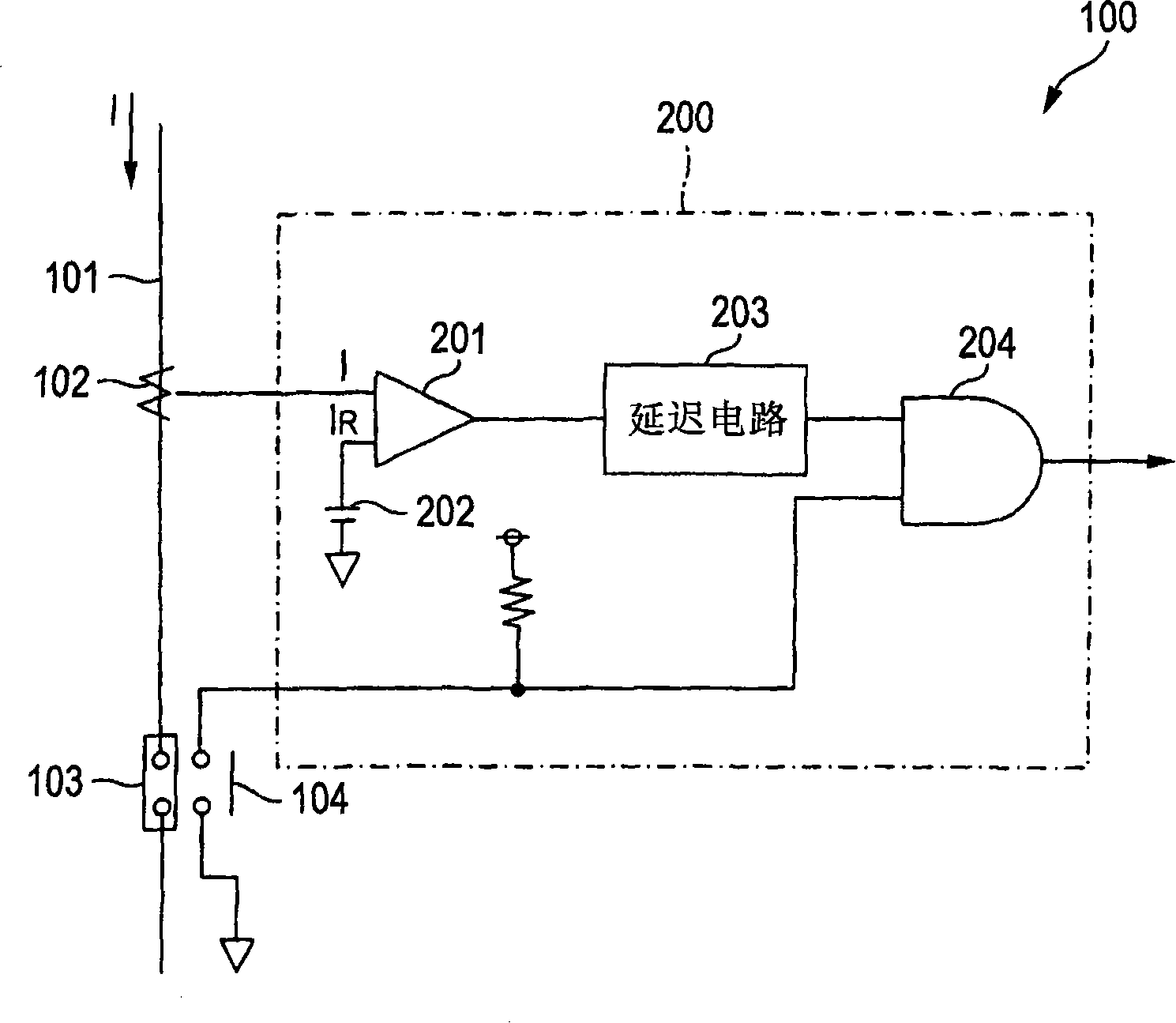
[0014] figure 1 It is a circuit diagram showing the state monitoring device of a circuit breaker according to Embodiment 1 of the present invention. exist figure 1 Among them, the circuit breaker 100 is built with: a current detector 102, which detects the energized current flowing through the circuit 101; a main contact 103, which cuts off the energized current when the energized current is greater than or equal to a specified value; and an auxiliary switch 104, which is connected to the The main contact 103 is linked to detect the tripping state. Furthermore, the circuit breaker 100 is provided with a state monitoring device 200 which monitors the operating state of the circuit breaker and outputs an alarm signal when the operating state is abnormal.
[0015] In this state monitoring device 200, the overcurrent detection comparator 201 compares the current value I detected by the current detector 102 with the reference current value I set by the current setter 202. R , wh...
Embodiment approach 2
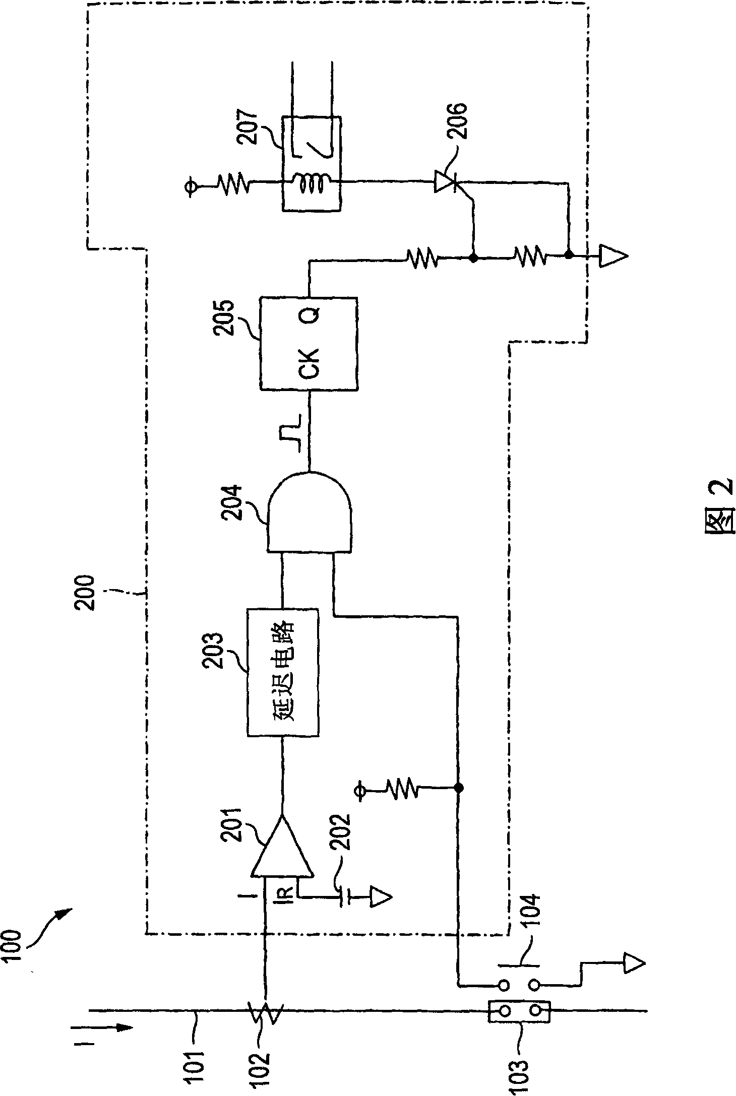
[0020] FIG. 2 is a circuit diagram showing Embodiment 2 of the present invention. In FIG. 2 , the structure up to the AND circuit 204 is the same as that of the first embodiment.
[0021] In Embodiment 2, the output signal of the AND circuit 204 by the counter 205, that is, even though the energized current value I is greater than the reference current value I R On the other hand, the electromagnetic reaction force is applied to the movable contact, and the number of occurrences of the state signal that the circuit breaker is not in the trip state is counted. The counter 205 stores the number of times that the consumption of the main contact 103 reaches a predetermined value, and if the number reaches the number, a signal is output to turn on the semiconductor switching element 206 , and the relay unit 207 outputs an alarm signal. In addition, the relay unit 207 may be replaced with another unit which notifies that the contact is depleted, such as an LED.
[0022] In the cir...
Embodiment approach 3
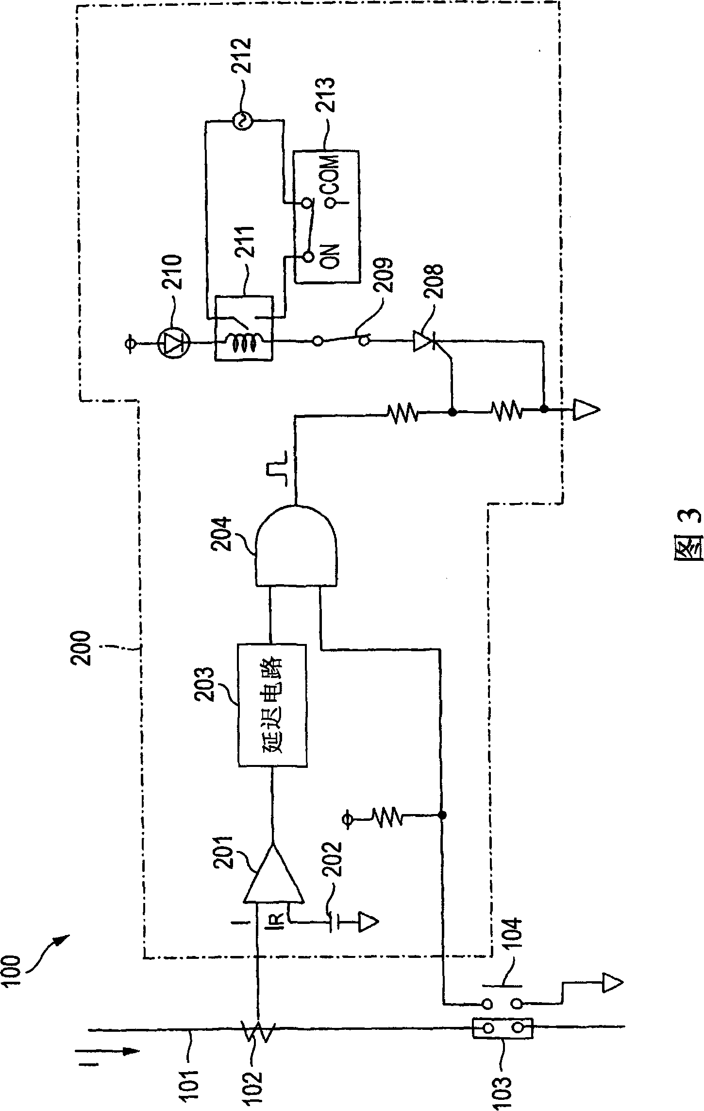
[0024] FIG. 3 is a circuit diagram showing Embodiment 3 of the present invention. In FIG. 3 , the structure up to the AND circuit 204 is the same as that of the first embodiment.
[0025] In Embodiment 3, if the signal of the AND circuit 204 is output, that is, even though the conduction current value I is greater than the reference current value I R On the other hand, the electromagnetic reaction force acts on the movable contact, and the signal that the circuit breaker is not tripped is output, the semiconductor switching element 208 is turned on, and the output from the relay unit 211 is generated, and the circuit breaker is electrically opened by the power supply 212. Closed electrical operating device 213, the circuit breaker is turned off and then turned on.
[0026] Here, since the circuit breaker cannot be disconnected if the main contact 103 is welded, the auxiliary switch 209 for detecting the open / closed state of the circuit breaker is kept closed, and the LED 210 ...
PUM
 Abstract
Description
Claims
Application Information
 - R&D
- Intellectual Property
- Life Sciences
- Materials
- Tech Scout
- Unparalleled Data Quality
- Higher Quality Content
- 60% Fewer Hallucinations
Browse by: Latest US Patents, China's latest patents, Technical Efficacy Thesaurus, Application Domain, Technology Topic, Popular Technical Reports.
© 2025 PatSnap. All rights reserved.Legal|Privacy policy|Modern Slavery Act Transparency Statement|Sitemap|About US| Contact US: help@patsnap.com


