Minitype inertial electrical switch capable of regulating and controlling contact time

A contact time, miniature technology, applied in the direction of electrical switches, circuits, electrical components, etc., can solve the problems of unadjustable contact time, no boundary protection of the mass block, damage to the device, etc., to improve the contact effect, facilitate the contact time, increase the The effect of coordination

Inactive Publication Date: 2008-05-07
SHANGHAI JIAO TONG UNIV
View PDF0 Cites 17 Cited by
  • Summary
  • Abstract
  • Description
  • Claims
  • Application Information

AI Technical Summary

Problems solved by technology

When the mass block electrode collides with another fixed electrode directly on the substrate, the contact effect is not good due to the high stiffness of both, and the contact time is short and cannot be adjusted. In addition, the mass of high-speed rebound block does not have any boundary guards and may result in device damage

Method used


Image

  • Minitype inertial electrical switch capable of regulating and controlling contact time
  • Minitype inertial electrical switch capable of regulating and controlling contact time
  • Minitype inertial electrical switch capable of regulating and controlling contact time

Examples


Embodiment 1

[0027] Embodiment 1 A miniature inertial electrical switch with adjustable contact time with a pair of porous elastic beam fixed electrodes

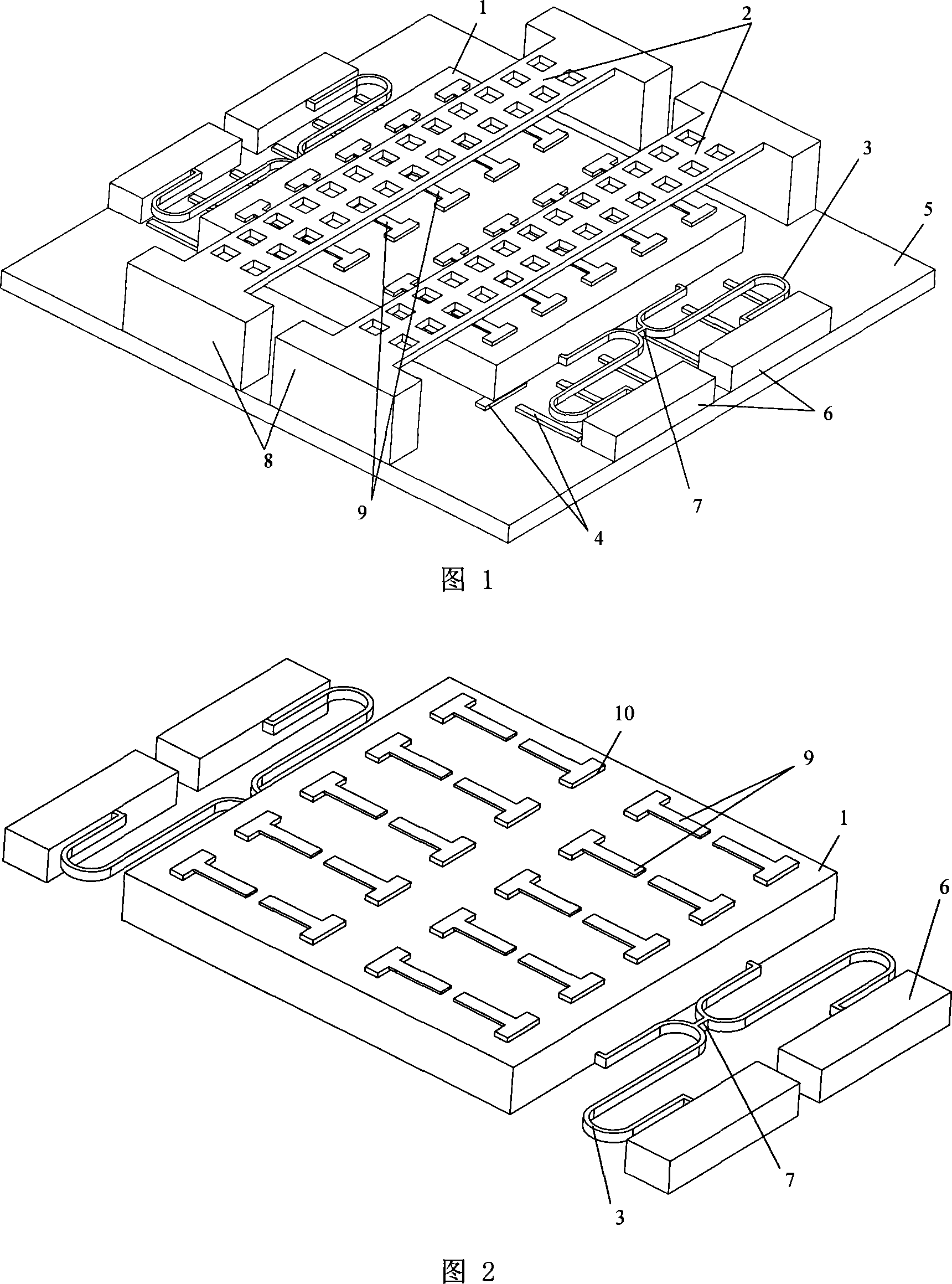
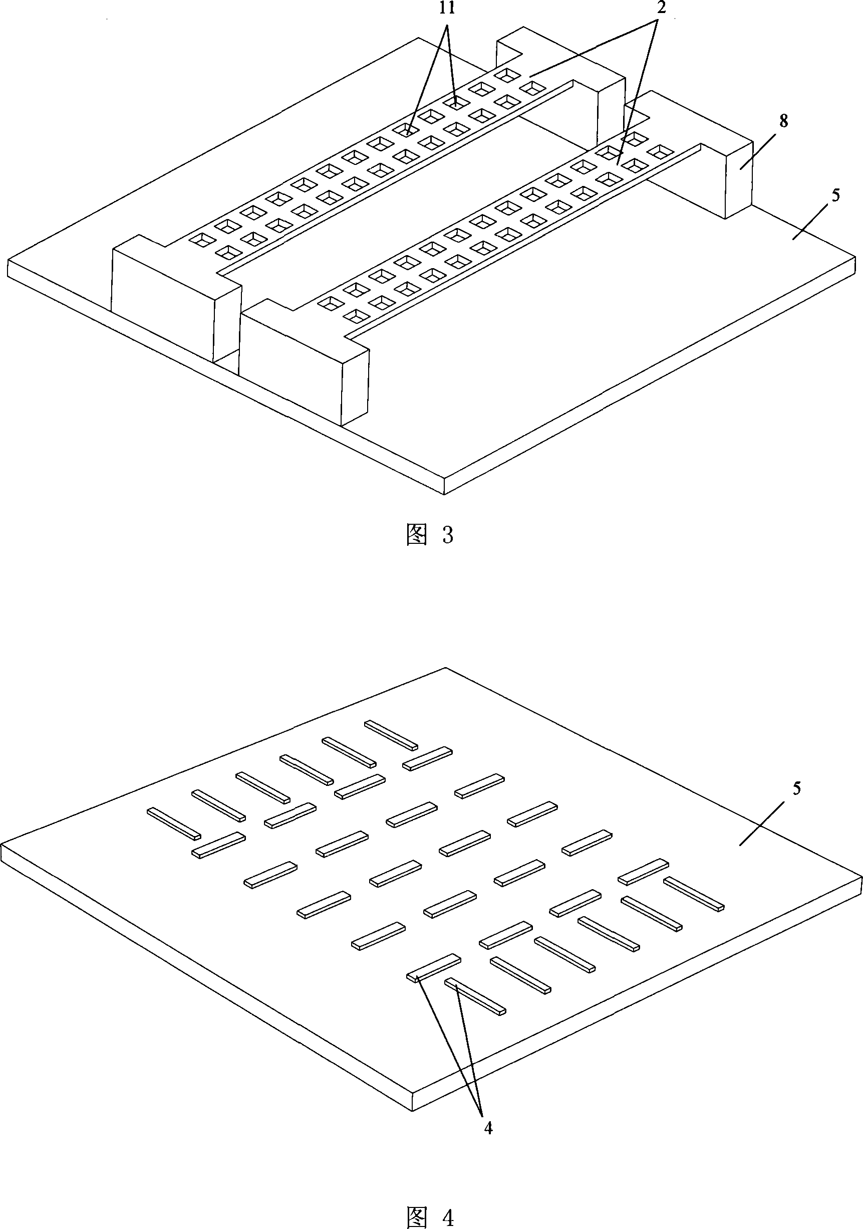
[0028] As shown in Figure 1, the micro-inertial electrical switch that can control the contact time in this embodiment includes: a mass electrode with a cantilever beam array, a porous elastic beam fixed electrode 2, a conjoined serpentine spring 3, a support layer 4, and an insulating lining Bottom 5, spring support seat 6, porous elastic beam support seat 8; the mass block electrode with cantilever beam array is composed of mass block 1 and cantilever beam array 9 fixed on mass block 1.

[0029] The support layer 4 is located above the insulating substrate 5 and below the mass block 1. The spring support base 6 is fixed on the insulating substrate 5 and located on both sides of the mass block 1. The porous elastic beam support base 8 is also fixed on the insulating substrate 5 and located on the On the other two sides of the mass block 1...

Embodiment 2

[0043] Embodiment 2 A micro-inertial electrical switch with adjustable contact time using a porous elastic beam

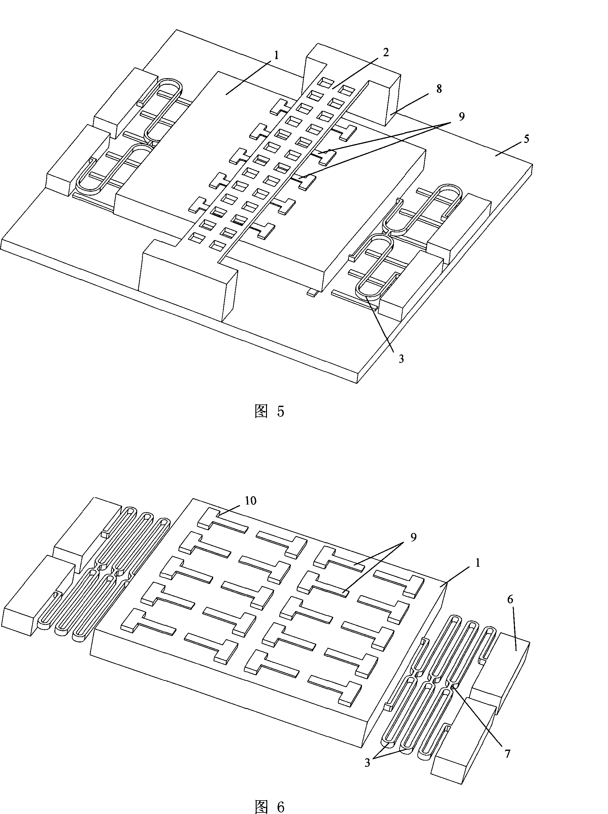
[0044] Fig. 5 is a three-dimensional schematic diagram of a micro-inertial electrical switch with an adjustable contact time using a porous elastic beam. As shown in the figure, the micro-inertial electrical switch uses a porous baffle beam as the fixed electrode 2 of the porous elastic beam. The size of the miniature inertial electrical switch is consistent with that of the miniature inertial electrical switch with adjustable contact time in Embodiment 1, and except for the fixed electrode 2 of the porous elastic beam, the shape and size of other components are consistent with Embodiment 1.

[0045] The contact time of the miniature inertial electrical switch in this embodiment can be adjusted between 20-100 microseconds.

Embodiment 3

[0046] Embodiment 3 A miniature inertial electrical switch with adjustable contact time with multi-turn conjoined serpentine springs

[0047] Fig. 6 is a structural schematic diagram of a miniature inertial electrical switch with adjustable contact time in this embodiment, as shown in the figure, the conjoined serpentine spring 3 used in the miniature inertial electrical switch is multi-turn, The remaining features of the miniature inertial electrode switch are similar to Embodiment 1.

[0048] The contact time of the miniature inertial electrical switch in this embodiment can be adjusted between 20-200 microseconds.


PUM


Abstract

The invention relates to a minitype inertia electrical switch which can adjust the contact time, belonging to the micro electromechanical system technical field. The invention is characterized in that: a mass block electrode with a cantilever beam array comprises a mass block and a cantilever beam array fixed to the mass block; the cantilever beam array is positioned below a fixed electrode of a porous elastic beam; a support layer is positioned above an insulated base and below the mass block; the support unit of a spring and the support unit of the porous elastic beam fixed to the insulated base are positioned around the mass block; a joint snake shaped spring connected with the mass block is hung in the air by the support unit of the spring; the fixed electrode of the porous elastic beam positioned above the mass block is hung in the air by the support unit of the porous elastic beam, and a gap is positioned between the fixed electrode of the porous elastic beam and the cantilever beam array. The invention has the advantages of improving the contact effect of the movable mass electrode and the fixed electrode of the elastic beam, adjusting the contact time of the two electrodes of the minitype inertia switch conveniently, and improving the coordination of the movement of the mass block with the joint snake shaped spring caused by the outside acceleration.

Description

technical field [0001] The invention relates to a micro-switch in the technical field of micro-electromechanical engineering, in particular to a micro-inertial electrical switch with adjustable contact time. Background technique [0002] Inertial switches designed and manufactured based on MEMS technology have attracted much attention due to their advantages of small size, low cost and mass production. In the past, the miniature inertia switch, whether it is vertical drive or horizontal drive, has its processing method developed on the traditional integrated circuit manufacturing technology. In many cases, the preparation of the switch is based on the silicon substrate. The inevitable internal stress in the process determines that the height of the entire device cannot be too thick. In order to have a large enough mass to sense the acceleration of the outside world, the overall area of ​​the device will eventually be large. This problem is driven by the horizontal. It is mo...

Claims


Application Information

Patent Timeline
Patent Type & Authority Applications(China)
IPC IPC(8): H01H35/14
Inventor 丁桂甫杨卓青蔡豪刚
Owner SHANGHAI JIAO TONG UNIV
Why Eureka
Try Eureka