Control valve type lead accumulator

A lead-acid battery and control valve technology, used in lead-acid batteries, electric vehicles, final product manufacturing, etc., can solve problems such as unusable machines, and achieve the effect of suppressing short circuits

Active Publication Date: 2008-05-07
GS YUASA INT LTD
View PDF1 Cites 8 Cited by
  • Summary
  • Abstract
  • Description
  • Claims
  • Application Information

AI Technical Summary

Problems solved by technology

[0008] However, the rapid capacity drop caused by a short circuit cannot be predicted in advance by the above-mentioned discharge voltage change and internal resistance change

Method used


Image

  • Control valve type lead accumulator
  • Control valve type lead accumulator

Examples


Embodiment

[0030] The following is a survey of the number of cycle life and the occurrence of short circuits for each test body of the valve-controlled lead-acid storage battery with various components of the negative electrode active material, the distance between the positive electrode plate and the negative electrode plate, and the reaction utilization rate of the negative electrode active material. , the test results are described as examples. The experimental bodies prepared here are all controlled lead storage batteries with a capacity of 12Ah and an electromotive force of 6V.

[0031]

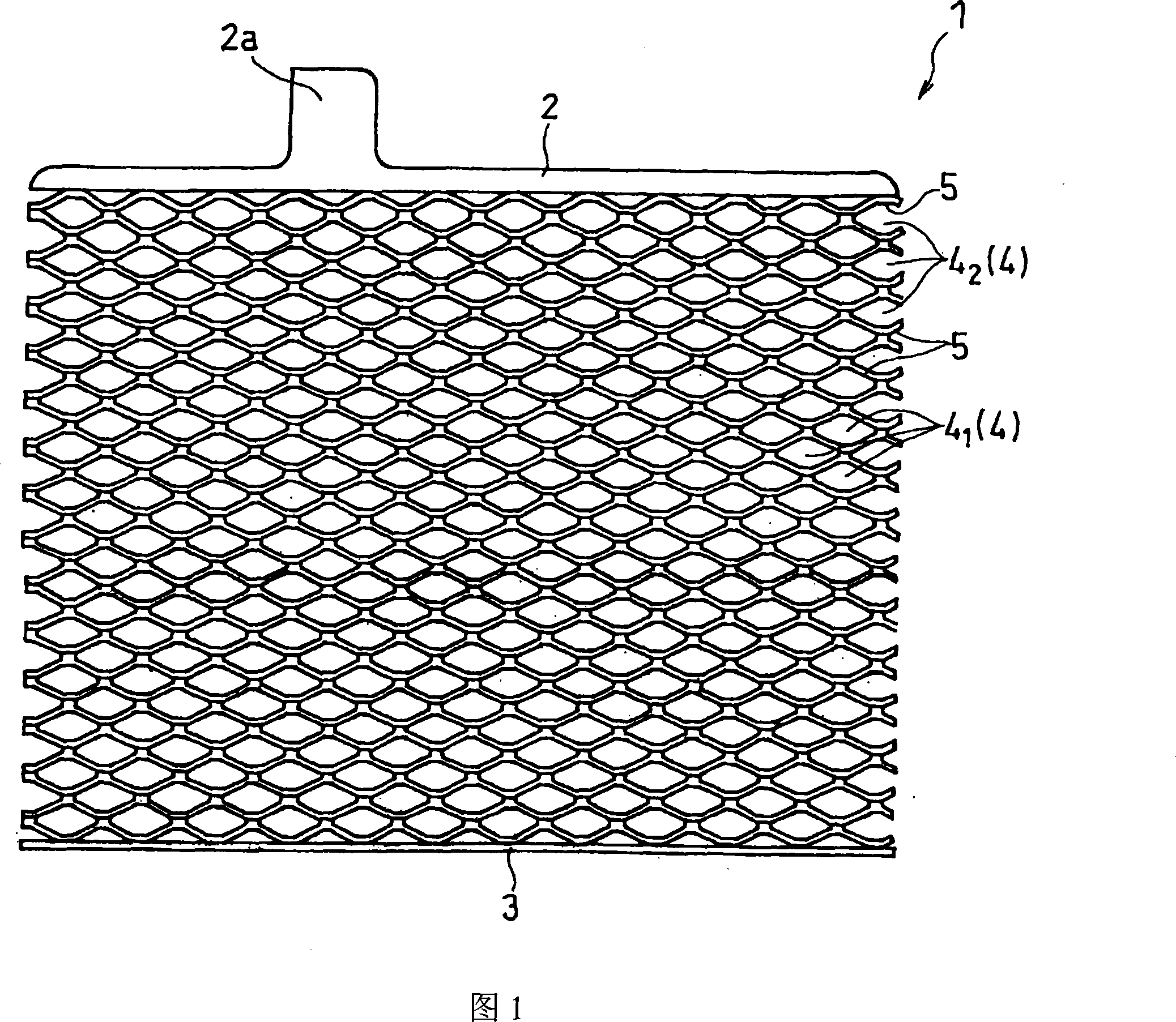
[0032]Ball mill (ball mill) lead powder (lead oxide with a degree of oxidation of 70%) is added with 10kg of water and 5kg of dilute sulfuric acid (density 1.300g / cm2 at 20°C) per 100g of lead powder. 3 ) for mixing to make negative electrode active material slurry (referred to as slurry PA). After the slurry PA is filled into each mesh 4 of the mesh metal grid 1 shown in FIG. 1 , it is aged and...


PUM


Abstract

A control valve type lead storage battery of the invention has a plate group composed of positive plates and negative plates which are alternately overlapped with each other, and a film is placed between every positive plate and negative plate. The positive and the negative plates contain multi-mesh grid bodies for active substance preservation, wherein, at least the grid body of the negative plates are composed of net-shape metal grid. The distance between a positive plate and a negative plate is 1.20mm or greater than the value, and the response utilization ratio of the active substances preserved in the meshes of the net-shape metal grid is 32.0% or lower than the value.

Description

technical field [0001] The present invention relates to a control valve type lead storage battery. Background technique [0002] In recent years, expanded metal grids have been increasingly used as plates for valve-controlled lead-acid batteries. The mesh metal grid system is: a plurality of slits are intermittently arranged in parallel on a lead alloy sheet (sheet), and after the linear part between the slits protrudes from the inside and outside of the sheet (sheet), the above-mentioned The sheet is stretched in a direction perpendicular to the slit, thereby forming a plurality of rhombic meshes for holding the active material (see FIG. 1 ). Because this mesh metal grid can be made thinner, it is superior to traditional cast grids. Therefore, by using the mesh metal grid for the pole plate of the valve-type lead-acid battery, it is possible to reduce the weight of the lead-acid battery and reduce the amount of lead alloy used for the pole plate. [0003] However, since ...

Claims


Application Information

Patent Timeline
IPC IPC(8): H01M10/06
CPCY02E60/126Y02T10/7016Y02E60/10Y02P70/50
Inventor 佐佐木健浩吉岭俊文藤森智贵中岛孝
Owner GS YUASA INT LTD
Why Eureka
Try Eureka