DNA separating micro-fluidic chip

A technology of microfluidic chips and flow channels, applied in stress-stimulated microbial growth methods, organic chemistry, sugar derivatives, etc., can solve problems such as deformation and damage of microfluidic chips, and the inability of DNA chains to be stretched effectively

Inactive Publication Date: 2008-05-14
JILIN UNIV
View PDF0 Cites 6 Cited by
  • Summary
  • Abstract
  • Description
  • Claims
  • Application Information

AI Technical Summary

Problems solved by technology

[0003] The flow channel structure of the current DNA separation microfluidic chip is a direct current channel. The DNA drive method of this structure is single, and it is only suitable for electr...

Method used


Image

  • DNA separating micro-fluidic chip
  • DNA separating micro-fluidic chip
  • DNA separating micro-fluidic chip

Examples


Embodiment Construction

[0021] The specific content of the present invention is further described below in conjunction with the embodiment shown in the accompanying drawings:

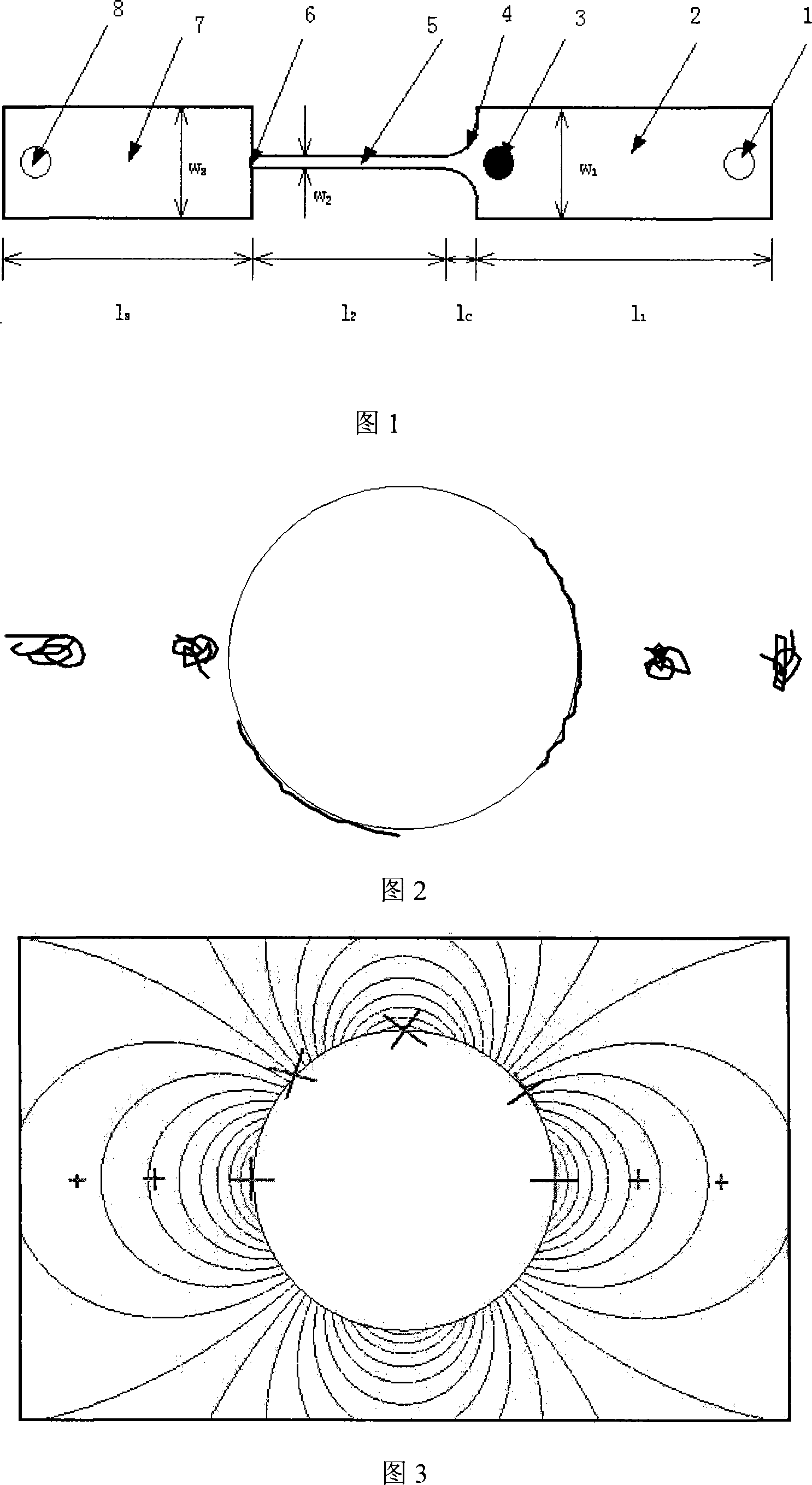
[0022] Referring to Fig. 1: the present invention includes: sample pool 1, inlet flow channel 2, front cylindrical obstacle 3, hyperbolic micro-constriction structure 4, slit flow channel 5, sudden expansion port 6, outlet flow channel 7, Waste liquid tank 8.

[0023] Set the size of the flow channel as follows: the length l of the inlet flow channel 2 1 =1.5mm, width w of inlet channel 2 1 =200 μm, the length l of the hyperbolic microcontraction structure 4 c =80 μm, the length l of the slit channel 5 2 =1.52mm, the width w of the slit channel 5 2 =3.8μm, the length l of the outlet channel 7 3 = 1.5mm, the width w of the outlet channel 7 2 =200μm, coefficient c=w 2 l c / (2-2w 2 / w 1 ) = 155μm 2 .

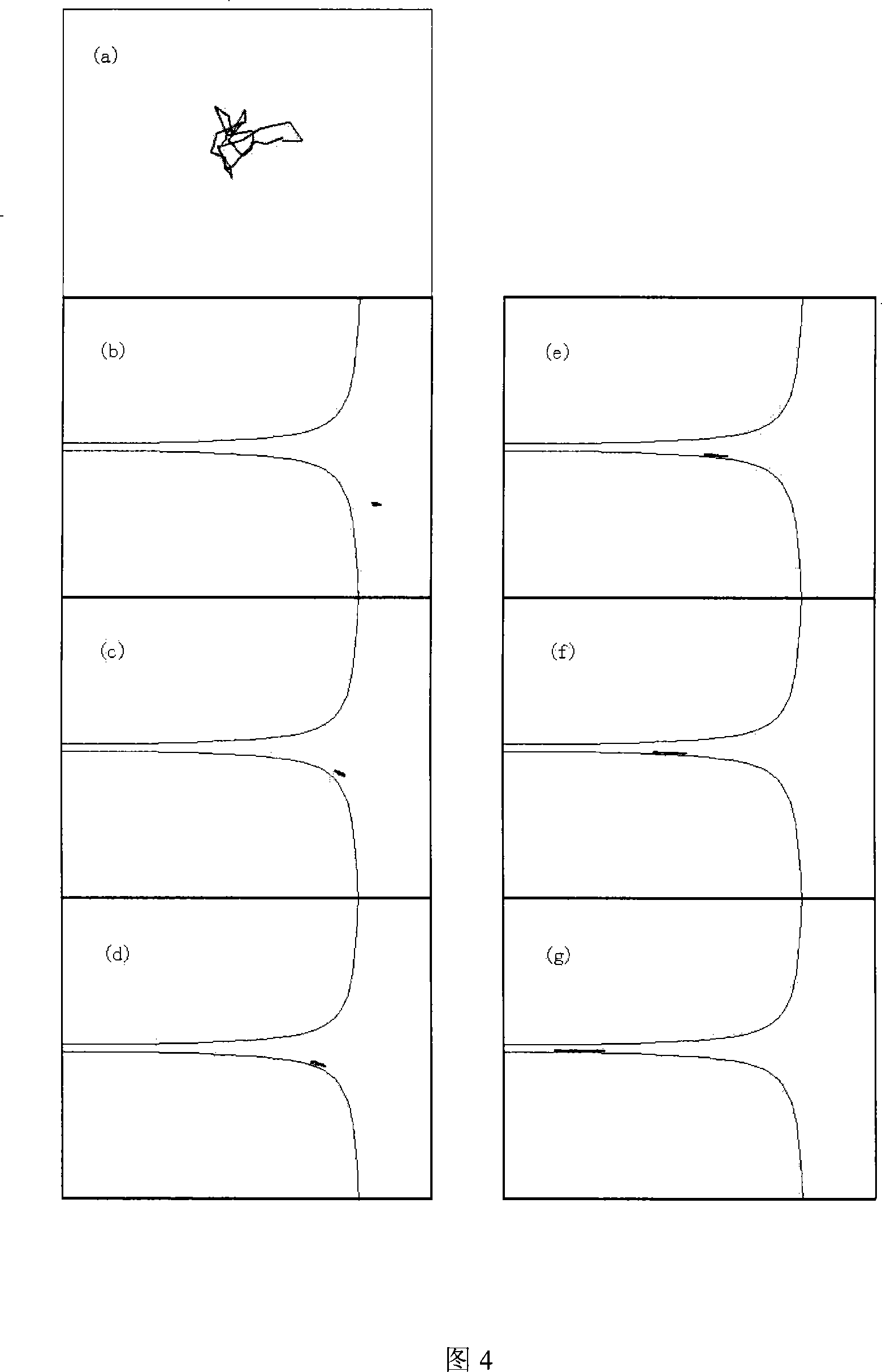
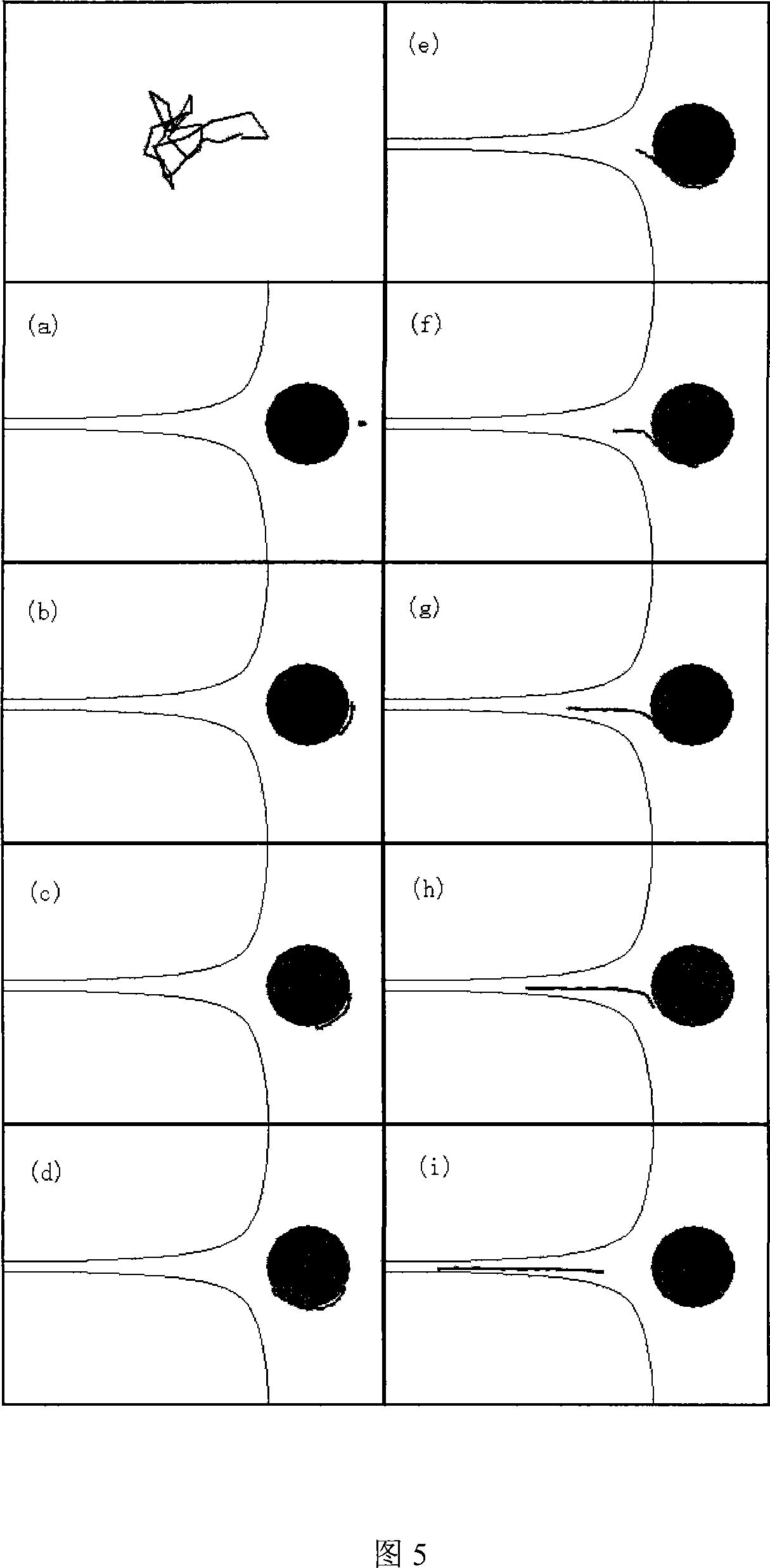
[0024] Driven by the force of the flow field or electric field, the DNA strand enters the microfluidic chip from the ...


PUM


Abstract

The invention relates to a novel structure of a micro-fluidic chip used for DNA separation, pertaining to the field of micro-fluidic chip design for separating DNA or large molecule, etc. The structure comprises a sampling inlet tank (1), an entrance channel (2), a hyperbola micro-shrinkage structure (4), a slit channel (5), a sudden enlarging mouth (6), an outlet channel (7) and a waste liquor (8), which are communicated with each other in sequence; a cylinder-shaped barrier (3) is positioned inside the entrance channel (2) in front of the hyperbola micro-shrinkage structure (4); the cylinder-shaped barrier (3) is positioned on a central line of a micro-fluidic channel. By adopting the cylinder-shaped barrier as a pre-tensile structure, the radius of the cylinder-shaped barrier and the distance between the circle center and the hyperbola micro-shrinkage structure are adjustable according to the real requirements, so as to realize the tensile and the separation of a DNA-chain with different lengths and different original structures. The invention can be driven by flow field and electric field, and the object of the tensile and the separation can be spread to any polymer with a certain universal applicability.

Description

technical field [0001] The invention relates to a new structure in the field of microfluidic chip design for separation of DNA or biological macromolecules, in particular to a microfluidic structure coupled with a front cylinder and a hyperbolic contraction. Background technique [0002] In the implementation of the Human Genome Project, in order to draw a gene map, it is necessary to stretch the DNA to the maximum to improve the sequencing accuracy. With the help of various structures of the microfluidic chip, the DNA chain can be deformed to a certain extent, so as to achieve the purpose of stretching or separation. [0003] The flow channel structure of the current DNA separation microfluidic chip is a direct current channel. The DNA drive method of this structure is single, and it is only suitable for electric field drive. A high electric field strength can easily lead to deformation and damage of the microfluidic chip. Moreover, the structure cannot effectively stretc...

Claims


Application Information

Patent Timeline
IPC IPC(8): C12M1/42C07H21/04
Inventor 左春柽冀封曹倩倩
Owner JILIN UNIV
Why Eureka
Try Eureka