
Control panel of washing machine

A technology for a control panel and a washing machine, which is applied to other washing machines, washing devices, textiles, and papermaking, etc., can solve the problems of inability to install a second operation button 20B, increase the installation space of the second operation button 20B, etc., and improve space utilization. , to achieve the effect of miniaturization and easy design

Inactive Publication Date: 2008-05-14
NANJING LG PANDA APPLIANCES
View PDF0 Cites 5 Cited by
  • Summary
  • Abstract
  • Description
  • Claims
  • Application Information

AI Technical Summary

Problems solved by technology

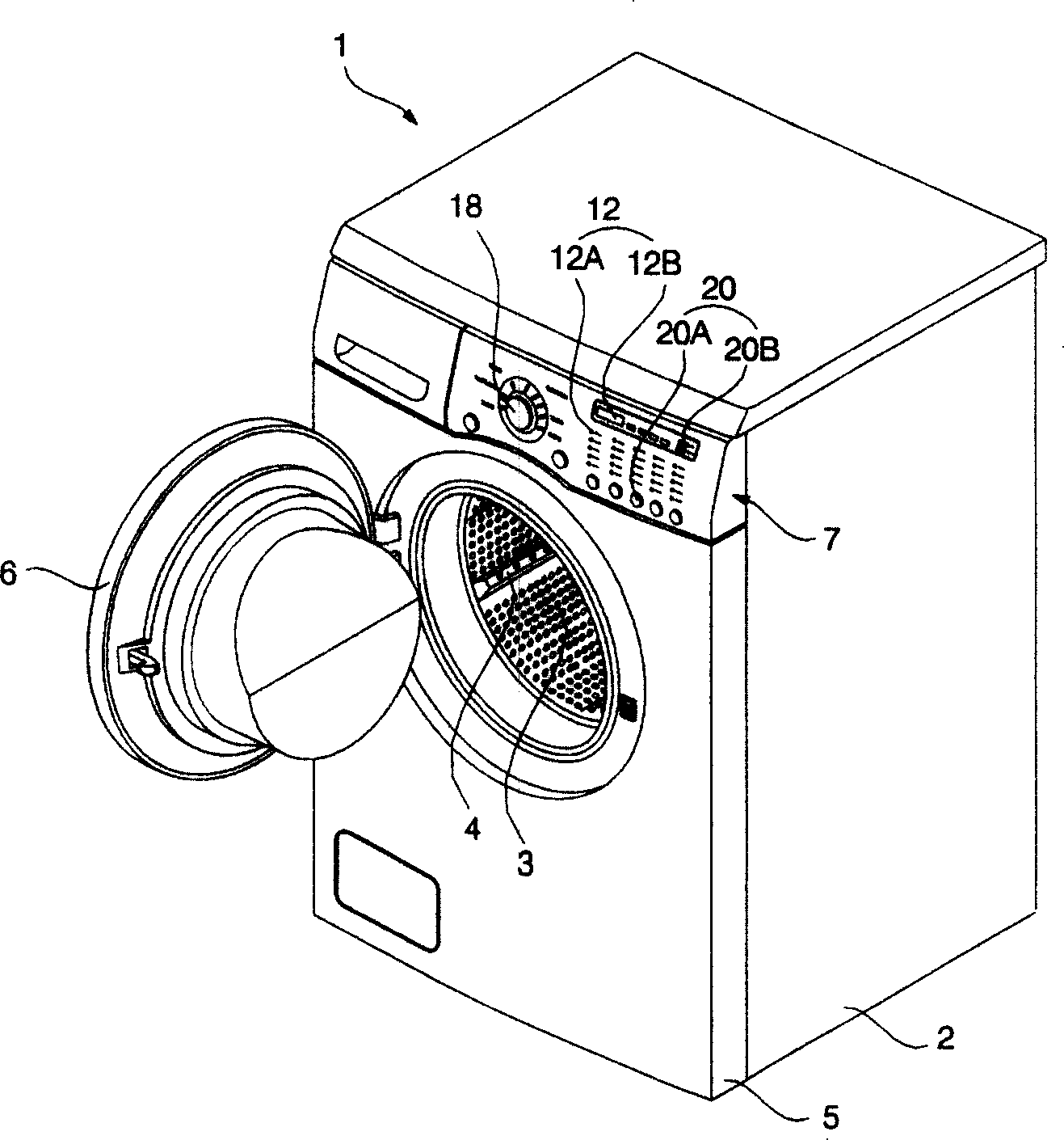
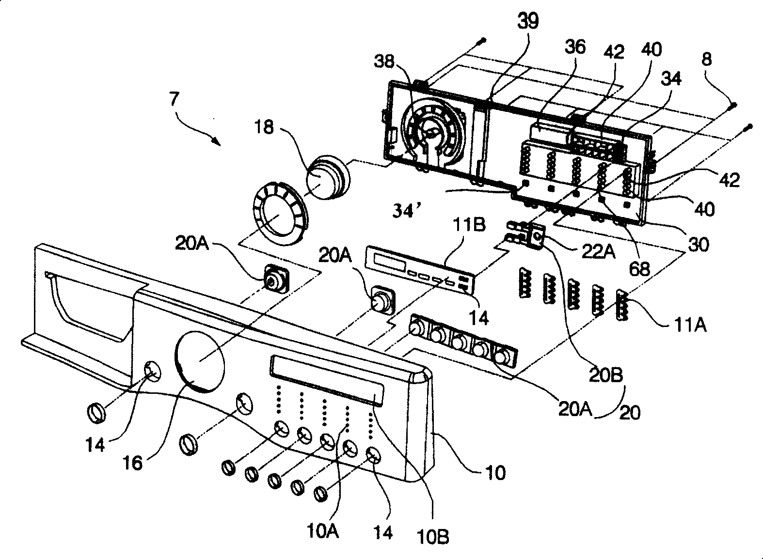
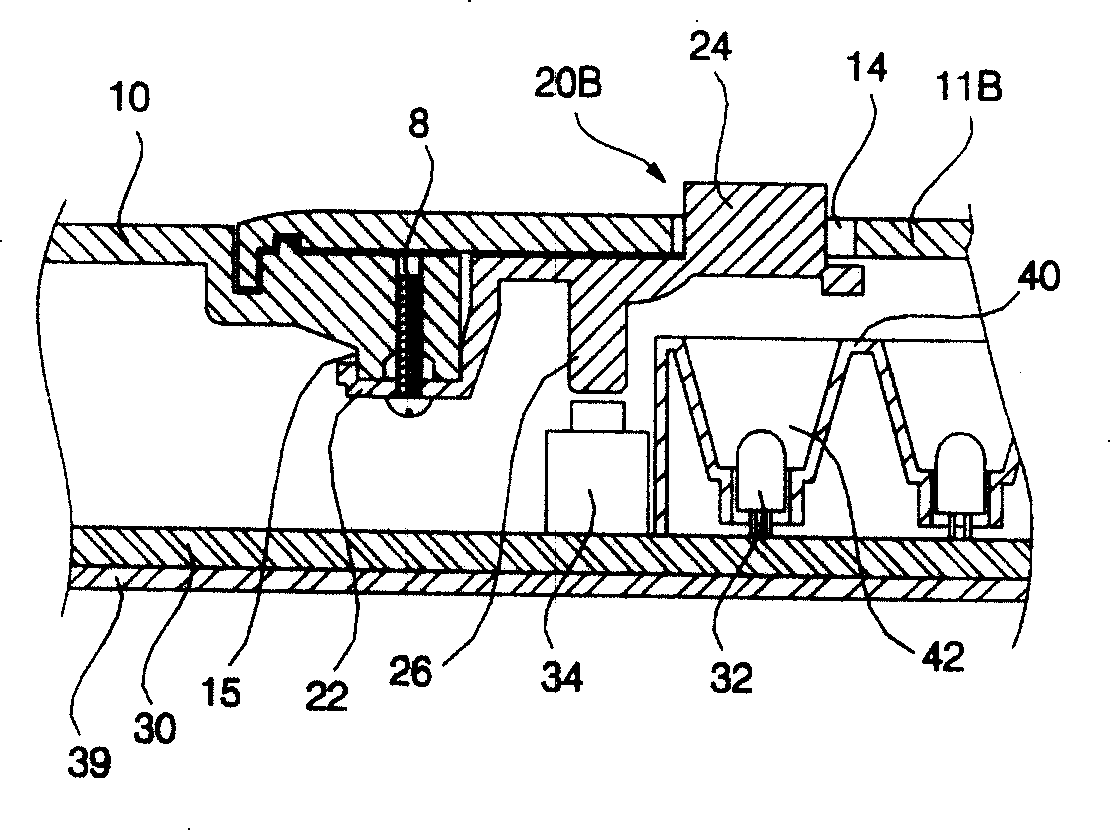
However, the washing machine control panel of this technology has the following problems: in order to arrange the second operation button 20B, it is necessary to protrude and form the assembly head 15 with a certain height on the back side of the front panel 10, so if there is a gap between the front panel 10 and the printed circuit board 30 If there is no space for installing the assembly head 15, the second operation button 20B cannot be installed.
In addition, although the light-emitting diode 32 is positioned at the inner side of the light-emitting diode support 40, the push switch 34 is positioned at the outside of the light-emitting diode support 40. The front of the front, the second operation button 20B needs to be arranged on the back of the front panel 10 in a cantilever manner, which will not only increase the installation space of the second operation button 20B, but also can only arrange the second operation button 20B on the edge of the LED pillar 40 The front of the part, so when installing the second operation button 20B, it is restricted by space

Method used


Image

  • Control panel of washing machine
  • Control panel of washing machine
  • Control panel of washing machine

Examples


Embodiment Construction

[0034] The control panel of the washing machine provided by the present invention will be described in detail below in conjunction with the accompanying drawings and specific embodiments. The same reference numerals are used for the same parts as those in the prior art, and their descriptions are omitted. Such as Figure 4 to Figure 7 As shown, the control panel 50 of the drum washing machine provided by the present invention includes a front panel 60 which is installed on the drum washing machine 1 and constitutes the front face of the control panel 50, on which a transparent window 62, a button hole 64 and a knob hole 66 are formed; The operating knob 70 is arranged in the knob hole 66 in a rotatable manner; the operation button 80 is arranged in the button hole 64 in a pushable manner; it is arranged at the rear of the front panel 60 at a certain distance, and a light emitting diode 92 is arranged on it and the printed circuit board 90 of parts such as push switch 94; The...


PUM


Abstract

The invention discloses a control panel of a washing machine. The control panel comprises a front panel that is arranged on one side of the washing machine and is provided with a button hole, an operation button one end of which is hung on the back of the front panel and the other end of which is arranged in the button hole in a clicking way, a printed circuit board that is at the back of the front panel and is provided with a light emitting diode and a clicking switch and a support that is arranged on the printed circuit board used for supporting the light emitting diode and the clicking switch; one side of the support is provided with a guide part that can guide the light from the light emitting diode to a specific position, with the other side being provided with a pressing part that can transfer the pressing stress applied to the operation button to the clicking switch. The control panel of the washing machine of the invention can not only arrange the components on the printed circuit board compactly, thus improving space utilization rate of the printed circuit board, but also can install the components effectively on the small area of the printed circuit board.

Description

technical field [0001] The invention relates to a control panel of a washing machine, in particular to a washing machine capable of compactly placing components on a printed circuit board, thereby improving the space utilization rate of the printed circuit board, and allowing operation buttons to be arranged in a narrow space control panel. Background technique [0002] Generally, a washing machine is a device that uses water and detergent and mechanical action to remove pollutants from laundry, bedding, and other laundry through processes such as washing, rinsing, dehydration, and drying. figure 1 It is a structural perspective view of a drum washing machine with a control panel in the prior art. figure 2 for figure 1 The exploded perspective view of the control panel structure in . image 3 for figure 1 Sectional view of the partial structure of important parts of the control panel in . Such as Figure 1 to Figure 3 As shown, this prior art drum washing machine 1 ma...

Claims


Application Information

Patent Timeline
Patent Type & Authority Applications(China)
IPC IPC(8): D06F39/00
Inventor 朴惠用金宝演金铉奭李承热
Owner NANJING LG PANDA APPLIANCES
Learn More