Single-cavity double-oscillator piezoelectric pump

A dual vibrator and piezoelectric pump technology, which is applied in the direction of pumps, pumps with flexible working elements, liquid variable capacity machinery, etc., can solve the problems of low output flow and limited output capacity of single-cavity piezoelectric pumps, and achieve improved The effect of output ability

Inactive Publication Date: 2008-05-14
JILIN UNIV
View PDF0 Cites 19 Cited by
  • Summary
  • Abstract
  • Description
  • Claims
  • Application Information

AI Technical Summary

Problems solved by technology

[0004] The present invention provides a single-cavity double-oscillator piezoelectric pump to solve the problem that the output capacity of the single-cavity piezoelectric pump is limited by mechanical power and electric power, and the output flow rate is relatively low.

Method used


Image

  • Single-cavity double-oscillator piezoelectric pump

Examples


Embodiment 1

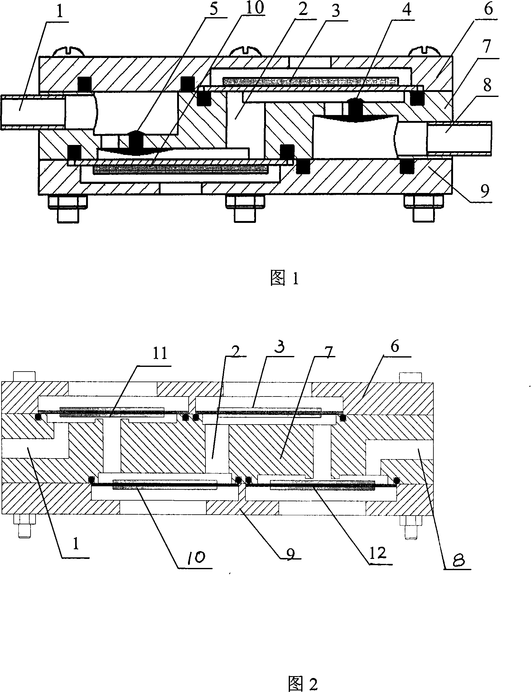
[0014] Referring to Fig. 1, the upper cover 6 and the lower cover 9 are fixedly connected to the pump body 7, the inlet pipe 1 and the outlet pipe 8 are fixedly connected to the water inlet and outlet of the pump body respectively, and the front part of the pump chamber 2 is fixedly connected to the pump chamber driving piezoelectric Vibrator one 10 is fixedly connected to the one-way passive valve one 5 at the water inlet of the pump chamber, fixedly connected to the pump chamber driving piezoelectric vibrator two 3 at the rear of the pump chamber 2, and fixedly connected to the one-way passive valve at the water outlet of the pump chamber Two 4.

[0015] Its working process has two states:

[0016] 1. The volume of the pump cavity is expanded. At this time, the piezoelectric vibrator expands outward at the same time, and the pressure in the pump body is lower than the external pressure. Under the action of the fluid pressure, the inlet valve opens, the outlet valve closes, a...

Embodiment 2

[0019] The upper cover 6 and the lower cover 9 are fixedly connected to the pump body 7, the inlet pipe 1 and the outlet pipe 8 are respectively fixedly connected to the water inlet and outlet of the pump body, and the front part of the pump chamber 2 is fixedly connected to the piezoelectric vibrator 10 driven by the pump chamber. The active valve one 11 is fixedly connected to the water inlet of the pump chamber, the pump chamber driving piezoelectric vibrator two 3 is fixedly connected to the rear of the pump chamber 2, and the active valve two 12 is fixedly connected to the water outlet of the pump chamber.

[0020] The first piezoelectric vibrator driven by the pump cavity and the second piezoelectric vibrator driven by the pump cavity adopt a bimorph circular piezoelectric vibrator. Active valve 1 and active valve 2 use a bimorph circular piezoelectric vibrator.

[0021] The working process of the pump is as follows:

[0022] 1. Apply an electrical signal to the piezoel...


PUM


Abstract

The invention relates to a single-chamber dual-vibrator piezoelectrical pump, belonging to the mechanical field of micro-electronic fluid. A pump body is fixedly connected between an upper cover and a lower cover; an inlet pipe and an outlet pipe are respectively and fixedly connected with the water inlet and a water outlet of the pump body; the front part of a pump chamber is fixedly connected with a pump chamber driving piezoelectrical vibrator 1; the water inlet of the pump chamber is fixedly connected with a check driven valve 1 or a drive valve 1; the invention is characterized in that the rear of the pump chamber is fixedly connected with a pump chamber piezoelectrical vibrator 2; the water outlet of the pump chamber is fixedly connected with a check driven valve 2 or a drive valve 2. The invention has the advantage that as the piezoelectrical vibrator has the advantages of fast responding, no electromagnetic interference, etc., the two drive vibrators in the pump chamber are led to keep harmonious and consistent, thus increasing the output flux and improving the output performance of the piezoelectrical pump.

Description

technical field [0001] The invention belongs to the field of microelectronic fluid machinery, and relates to a volume change mode of a pump chamber of a piezoelectric pump and two control modes of active control and passive control of a pump valve. Background technique [0002] Research on piezoelectric pumps began in the late 1980s. In 1978, W.J.Spenser of the Sandia National Laboratory in the United States published "Electrically Controlled Piezoelectric Insulin Pumps and Valves"; in 1980, Smits of Standora University proposed a piezoelectric liquid peristaltic pump; three years later, the University of Twente in the Netherlands used silicon micromachining and thin-film technology developed a number of piezoelectric-driven micropumps. With the continuous development of piezoelectric actuators, from piezoelectric material films to disc-shaped piezoelectric actuators to piezoelectric stacks, the types of piezoelectric actuators have been continuously updated, based on diffe...

Claims


Application Information

Patent Timeline
Patent Type & Authority Applications(China)
IPC IPC(8): F04B43/04
Inventor 程光明李鹏曾平庞建志董景石胡雄海
Owner JILIN UNIV
Why Eureka
Try Eureka