Glass metal sealing device of intermediate temperature solar heat pipe receivers

A technology of solar heat pipe and glass metal, which is applied in the field of sealing devices, can solve the problems of many solder joints, sealing and thermal expansion hindering wide application, increasing unreliability, etc., and achieves the effects of prolonging service life, cheap sealing structure, and convenient processing

Inactive Publication Date: 2008-05-14
NANJING UNIV OF TECH
View PDF0 Cites 5 Cited by
  • Summary
  • Abstract
  • Description
  • Claims
  • Application Information

AI Technical Summary

Problems solved by technology

However, a key technology involved in it-the sealing and thermal expansion between the vacuum glass sleeve and the heat absorbing tube has always hindered the wide application of this technology.
Therefore, the sealing structure used in such a parabolic trough receiver has the following disadvantages: ①...

Method used


Image

  • Glass metal sealing device of intermediate temperature solar heat pipe receivers
  • Glass metal sealing device of intermediate temperature solar heat pipe receivers
  • Glass metal sealing device of intermediate temperature solar heat pipe receivers

Examples


Embodiment 1

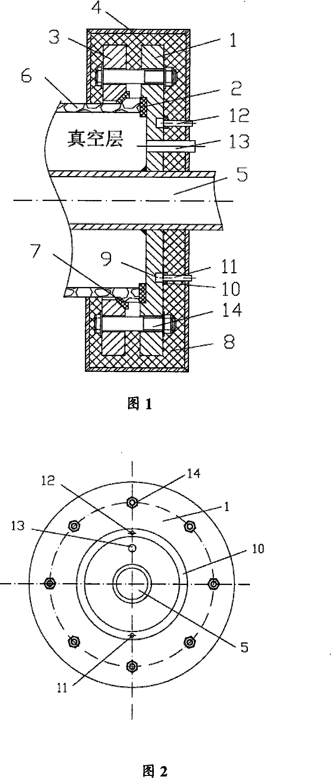
[0015] The specific structure of the glass-metal sealing device used in the medium-temperature solar heat pipe receiver of this embodiment is shown in Fig. 1 and Fig. 2 , including a metal cover 1 , a sealing ring 2 , a metal flange 3 and a shield 4 . The heat pipe 5 passes through the center of the metal cover 1 and is sealed and welded with the metal cover 1. The glass sleeve 6 and the metal cover 1 are sealed by the sealing ring 2. Bolts are respectively opened on the metal cover 1 and the metal flange 2. hole, the metal cover plate 1 and the metal flange plate 2 are connected by bolts 14, and after the bolts 14 are tightened, the metal cover plate 1, the sealing ring 2, the flanging of the glass casing 6, the anti-pressure gasket 7 and the metal flange The disc 3 is pressed tightly so that a vacuum layer is formed between the metal cover plate 1 , the glass casing 6 , the sealing ring 2 and the heat pipe 5 . A pressure-proof gasket 7 is installed between the metal flange 2...

Embodiment 2

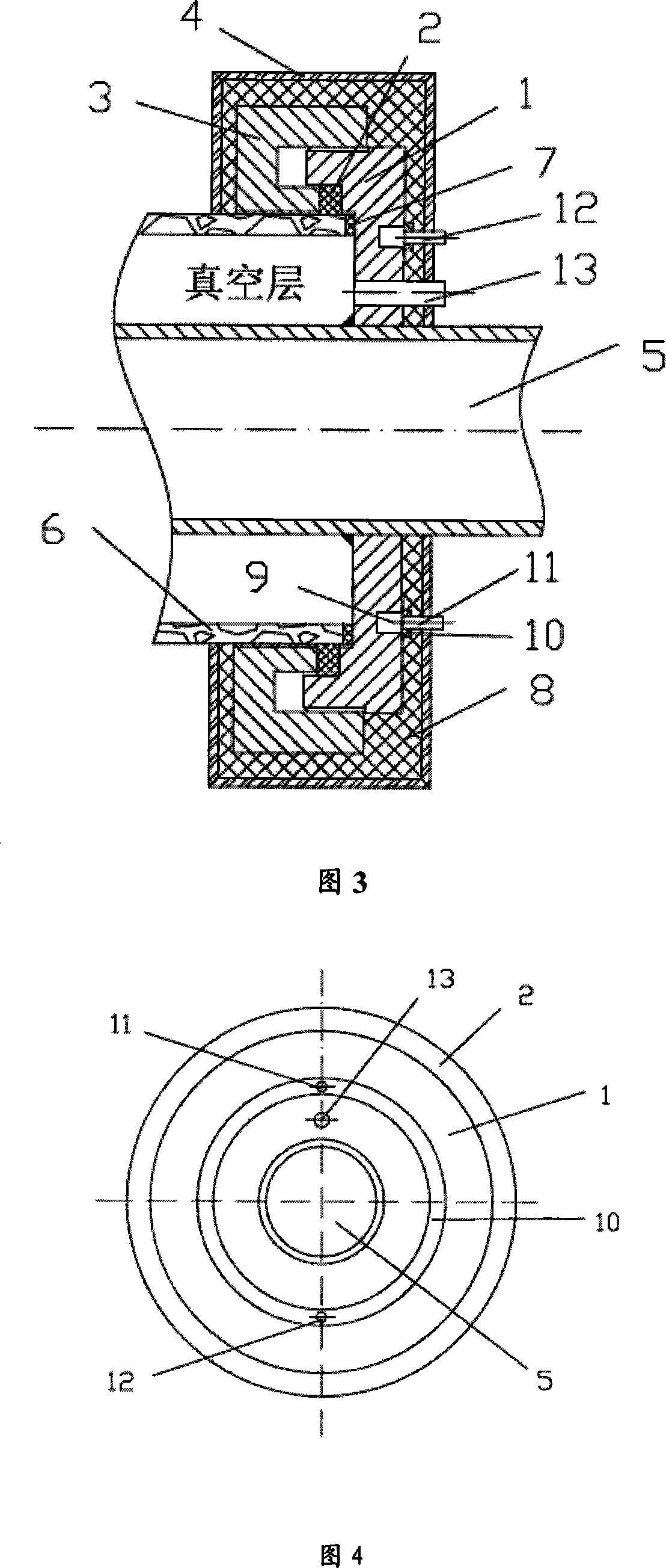
[0018] The specific structure of the glass-metal sealing device used in the medium-temperature solar heat pipe receiver of this embodiment is shown in Fig. 3 and Fig. 4, including a metal cover plate 1, a sealing ring 2, a metal flange 3, and a shielding cover 4. The heat pipe 5 passes through the center of the metal cover 1 and is sealed and welded with the metal cover 1. The glass sleeve 6 and the metal cover 1 are sealed by a sealing ring 2. Threads are respectively processed on the metal cover 1 and the metal flange 2. , through threaded connection, assembled screw thread, the metal cover plate 1, sealing ring 2, glass casing 6 and metal flange 3 are pressed tightly, so that the metal cover plate 1, glass casing 6, sealing ring 2, heat pipe 5 to form a vacuum layer, the contact surface between the metal cover plate 1 and the sealing ring 2 and the contact surface between the outer surface of the tube wall of the glass sleeve 6 and the sealing ring 2 are the sealing surfaces...


PUM


Abstract

The invention relates to a glass-metal sealing device for a medium-temperature solar heat pipe receiver. The structure of the present invention is that the heat pipe passes through the center of the metal cover plate and is sealed and welded with the metal cover plate. In the vacuum layer, an annular cooling groove is opened on the outside of the metal cover plate, and the shielding cover is arranged outside the sealing place. The invention solves the defects of the sealing structure of the parabolic trough receiver that the expansion coefficients of the glass-metal sealing parts should be strictly matched, too many solder joints, poor reliability, difficult processing and high price. The invention can sealingly connect glass and metal whose expansion coefficients do not match. There is a cooling water tank on the cover plate. When the working temperature of the receiver is 400°C, the temperature of the sealing ring is still lower than 200°C, which prolongs the life of the sealing device and will not cause deformation. Different thermal stress is generated, no expansion joint is required, the structure is simple, the processing is convenient, and the cost is low.

Description

technical field [0001] The invention relates to a sealing device, in particular to a glass-metal sealing device for a medium-temperature solar heat pipe receiver. Background technique [0002] Using a parabolic trough concentrator to focus solar energy and generate high-temperature steam for power generation is a solar thermal power generation technology with a relatively simple structure and low technical difficulty. However, a key technology involved therein——the sealing and thermal expansion problems between the vacuum glass casing and the heat-absorbing tube have always hindered the wide application of this technology. [0003] Before the present invention, the sealing structure used in the existing parabolic trough receiver was a Kovar alloy and glass fusion sealing structure. As shown in Figure 5, a vacuum was drawn between the glass casing 6 and the heat-absorbing steel pipe 15, and the glass casing The two ends of 6 are welded with transition metal 16, the transitio...

Claims


Application Information

Patent Timeline
IPC IPC(8): F24J2/05F24J2/32F24S10/40F24S10/95
CPCY02E10/44
Inventor 张红刘赟战栋栋李四海陈兴元陶汉中庄骏
Owner NANJING UNIV OF TECH
Why Eureka
Try Eureka