Accurate ground surface investigation method

A surface survey and precise technology, applied in seismic signal processing, seismic energy generation, etc., can solve problems such as difficult layout, low signal-to-noise ratio, and difficult picking, and achieve the effect of improving accuracy

Inactive Publication Date: 2008-05-14
孙素梅
View PDF0 Cites 20 Cited by
  • Summary
  • Abstract
  • Description
  • Claims
  • Application Information

AI Technical Summary

Problems solved by technology

For decades, field survey methods for low-velocity zones have been nothing more than small refraction methods and micro-logging methods. Compared with the rapid development of instrumentation and processing and interpretation methods, surface survey methods are old and single, and it is difficult to meet the requirements of high-precision seismic exploration.
[0003] 1. Problems in the application of small refraction: Since the thickness of the low-velocity zone is generally small, it is difficult to detect with the reflected wave method. Usually, the first-arrival refracted wave method is used to observe the direct waves and refracted wave
The data interpretation process in the work has the following problems: (1) Arranging in the field is easy to arrange when the terrain is flat, but it is not easy to arrange when the terrain is undulating. The data obtained by arranging and arranging in these areas often have large interpretation errors
(2) Small refraction has weak long-distance energy, low signal-to-noise ratio, and difficult to pick up at the first arrival
(3) Seismic traces are displayed at equal intervals during data interpretation, and the position of the inflection point is not easy to determine
(4) Only the time information is used in the small refraction interpretation method, but the waveform information is not used
[0004] 2. Problems in the application of micro-logging method: the current micro-logging construction methods are divided into three methods: surface receiving excitation in the well, receiving surface excitation in the well, and dual-well micro-logging methods in which the ground is stimulated in the well and the surface is received at the same time. Two methods of dual-well micro-logging: ground receiving in-well excitation, in-well excitation in-well, and surface receiving at the same time
(2) Although the vertical time-distance curve of the micro-logging can be used to divide the velocity layer in detail, it is often due to the fact that the actual formation is very different from the homogeneous average velocity assumed by the theory, such as the influence of thin high-speed layers, puddles and ditches, etc. , it is not easy to divide the velocity layer
(3) For static correction, it is generally only necessary to provide the velocity and thickness of the low, decelerating, and high-speed layers. Since the vertical time distance curve often lacks an obvious inflection point, it is difficult to divide the low and decelerating layers.

Method used


Image

  • Accurate ground surface investigation method
  • Accurate ground surface investigation method
  • Accurate ground surface investigation method

Examples


Embodiment Construction

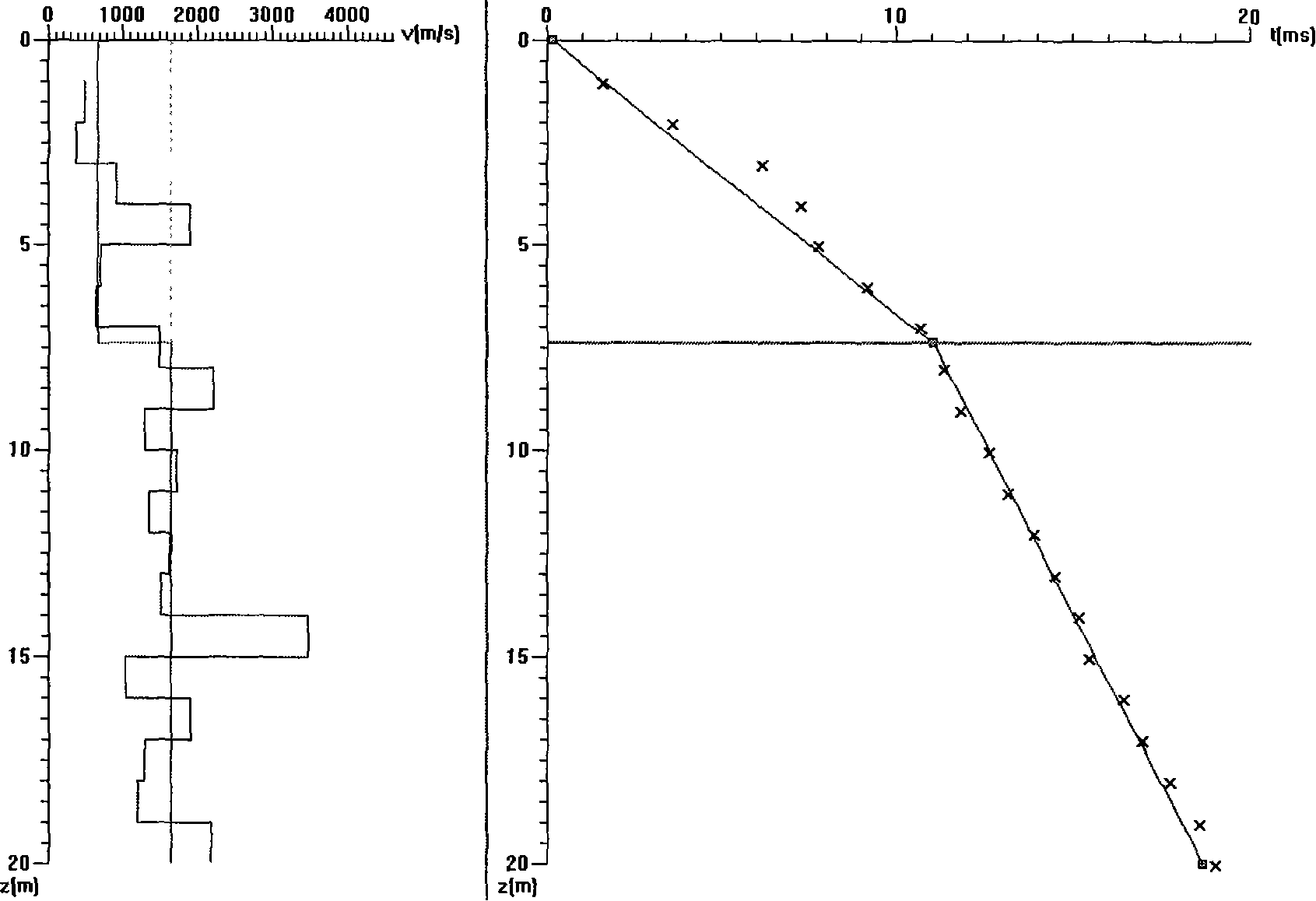
[0036] 1. Refraction micro-logging

[0037] The refraction micrologging method consists of two aspects, construction and interpretation.

[0038] The construction method is excitation in the well and reception on the ground (similarly, excitation on the ground and reception in the well can also be used), the difference is that the receiving channel is divided into two groups such as Figure 5 :

[0039] One group is the short track, the well detection distance is generally 1m to 5m (depending on the thickness of the low-speed zone), and 2-3 wells are used;

[0040] One group is the long distance, starting from 10 meters, 5 meters in a row, and the length is 50 meters.

[0041] Explanation method:

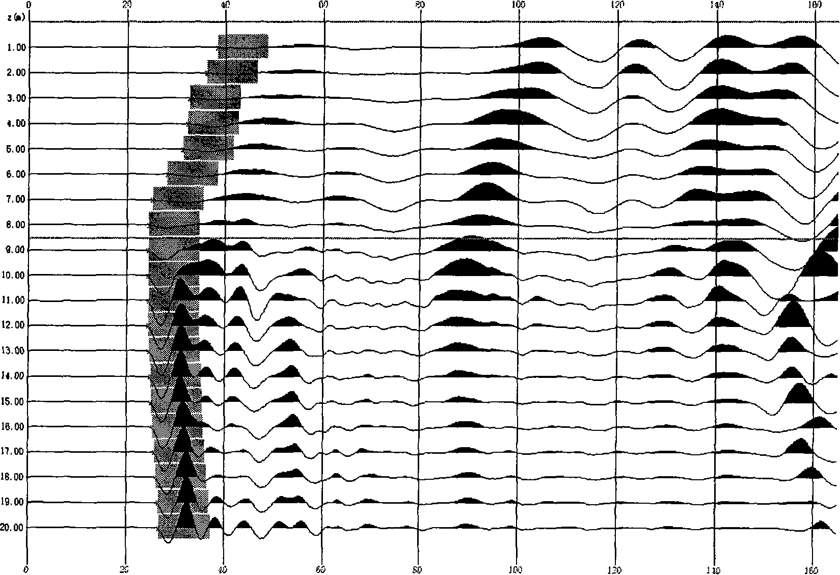
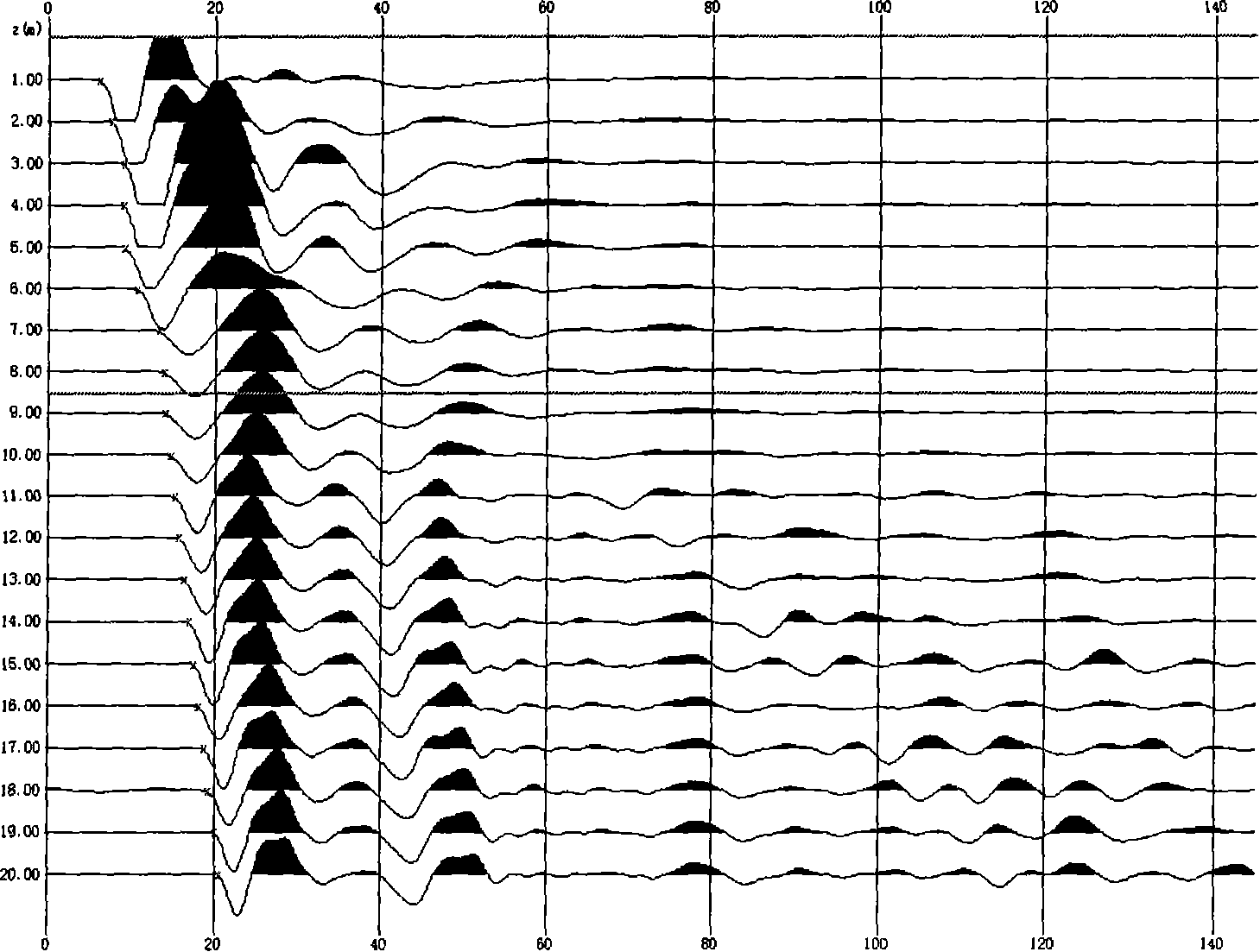
[0042] Firstly, by comparing the long-track waveform characteristics and distance characteristics between the excitation in the high-speed layer and the excitation in the low-speed layer, the velocity interface is obtained, such as figure 1 . Excited in the low-velocity layer, ...


PUM


Abstract

The invention relates to an accurate research method of landscape, namely, a surface layer research technology in the earthquake exploration, which overcomes the defect of other technology; a refraction micro-well method improves the construction method of the micro-well method, expanding to two groups of receiving of small well offset and large well offset from the original blasting in a well and small well offset receiving. An interface of a low-speed layer and a high-speed layer are obtained at a receiving point of the large well offset through the comparison of wave pattern and a time interval character so as to obtain the thickness information of the low-speed layer, and have precise speed explanation to the small well offset on the basis of the interface. Precise small refraction explanation is to explain directly by the matching proportion display of the small refraction and the actual distance. The initial picking precision is improved by far filter processing. Influence of the hypsography and nonuniform speed of the partial landscape is reduced by expanding subtraction calculation, improves the veracity of grouping and achieves the aim at improving the explanation precision.

Description

1. Technical field: [0001] The invention relates to a surface investigation technology in seismic exploration, especially an accurate surface investigation method. 2. Background technology: [0002] In recent years, with the continuous and in-depth development of seismic exploration, there are fewer and fewer exploration areas with good surface seismic geological conditions. We have to face areas with complex shallow surface seismic geological conditions such as mountains, hills, loess sources, and deserts. The terrain conditions in these areas are harsh and the surface structure is complex, which brings great difficulties to the field raw data collection and low-velocity zone investigation. In addition, the precision of surface investigation by high-resolution seismic survey teams puts forward higher requirements. For decades, field survey methods for low-velocity zones have been nothing more than small refraction methods and micro-logging methods. Compared with the rapid ...

Claims


Application Information

Patent Timeline
Patent Type & Authority Applications(China)
IPC IPC(8): G01V1/02G01V1/28
Inventor 孙素梅
Owner 孙素梅
Why Eureka
Try Eureka