Refrigeration compressor

A refrigerant and compressor technology, applied in mechanical equipment, machines/engines, liquid variable capacity machinery, etc., can solve problems such as large pressure, reduce volumetric efficiency, etc., and achieve the effect of reducing suction temperature

Inactive Publication Date: 2008-05-14
ACC AUSTRIA GMBH
View PDF1 Cites 3 Cited by
  • Summary
  • Abstract
  • Description
  • Claims
  • Application Information

AI Technical Summary

Problems solved by technology

However, this solution has the disadvantage that there is often a greater pressure drop during suction, which reduces the volumetric and thus energy efficiency more or less strongly

Method used


Image

  • Refrigeration compressor
  • Refrigeration compressor
  • Refrigeration compressor

Examples


Embodiment Construction

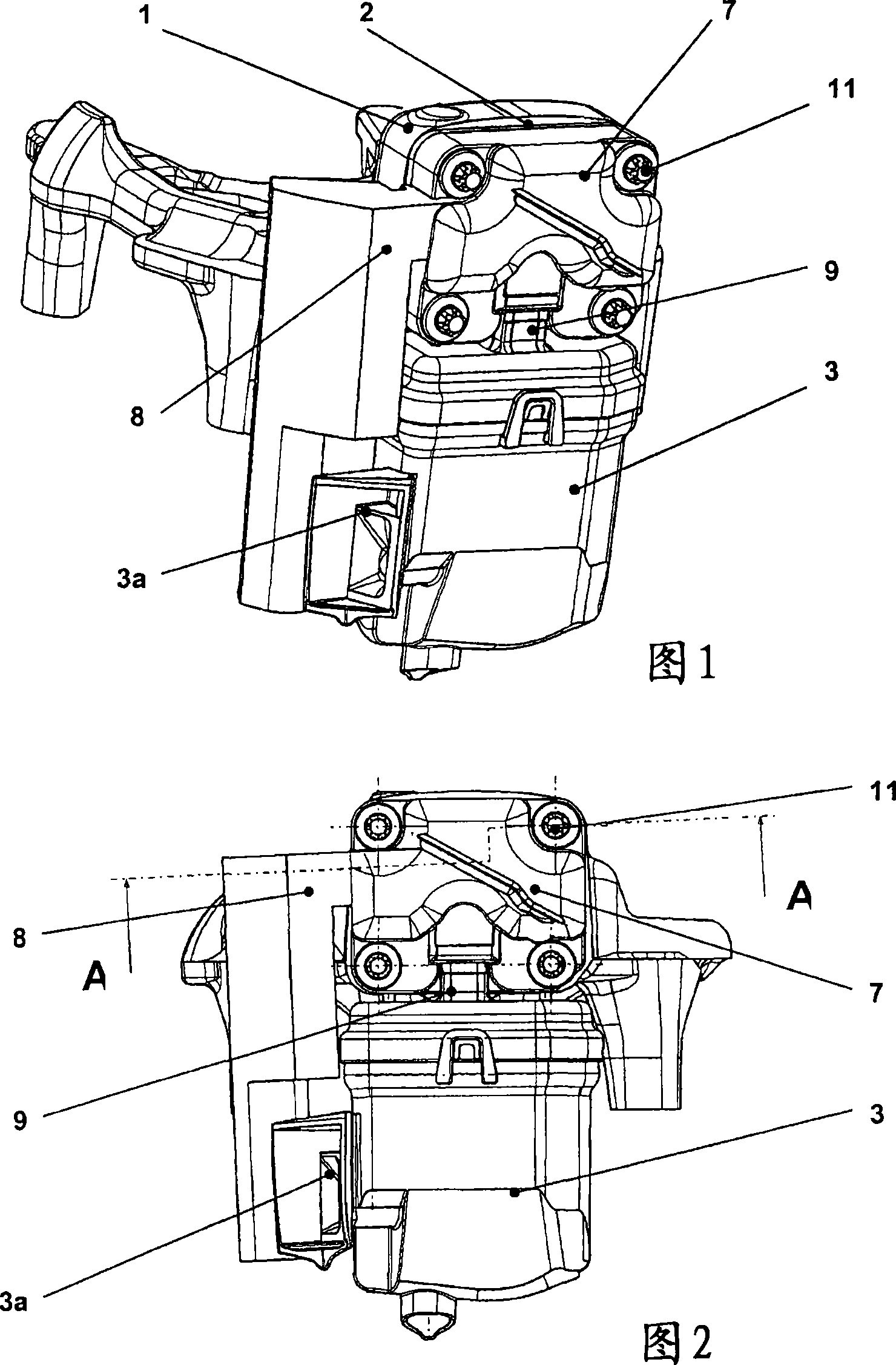
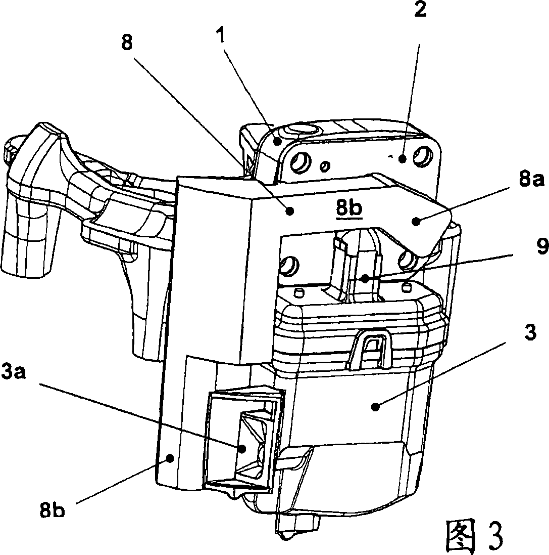
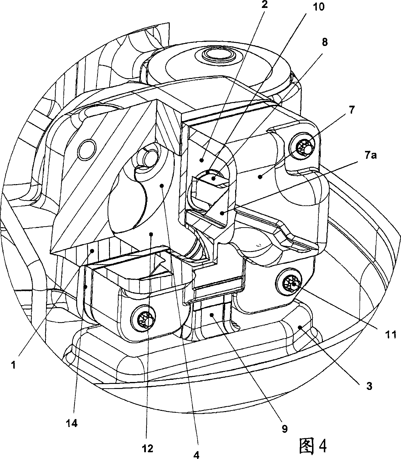
[0068] FIG. 1 shows an isometric view of a cylinder head according to the invention, in which individual parts of the cylinder block 1 , the valve plate 2 and the suction muffler 3 including the suction opening 3 a can be seen.

[0069] The basic structure of the subject hermetically sealed refrigerant compressor is known per se. The piston-cylinder-motor unit basically comprises a cylinder 1 and a piston 4 performing reciprocating motion therein, and crankshaft bearings 5 ​​in a crankcase 5a, perpendicular to the axis 6 of the cylinder. The crankshaft bearing 5 accommodates a crankshaft (not shown) and projects into a central bore of the rotor of an electric motor (also not shown), the rotational movement of which is transmitted via a connecting rod (not shown) in a manner also known per se. to piston 4. A suction muffler 3 is located on the cylinder head itself and it serves to minimize the noise output during the intake of the refrigerant.

[0070] Figures 1 and 2 show a ...


PUM


Abstract

The invention relates to a hermetically encapsulated refrigerant compressor with a hermetically tight compressor housing, within which a piston-cylinder unit for compressing refrigerant works, the cylinder of which is sealed by a valve plate (2), comprising a pressure drilling (10) and a suction drilling (16) and a suction channel and a pressure channel are also provided, by means of which refrigerant is sucked into the suction drilling (16) via a suction channel and from the pressure drilling (10) via a pressure valve (15), whereby a suction noise damper (3) is preferably arranged in the suction channel. According to the invention, preferably V-shaped sealing grooves (23), or sealing projections (22) are provided in the valve plate (2) and the component (9), forming the suction channel, is provided with sealing projections (22) or sealing grooves (23) essentially corresponding to the V-shaped sealing grooves (23) or sealing projections (22) on the front face thereof facing the valve plate (2) along the suction sealing edge (17), whereby the sealing projections (22) in the geometric form thereof have a different embodiment to the sealing grooves (23) and / or have a different volume.

Description

technical field [0001] The invention relates to a hermetically sealed refrigerant compressor according to the preamble of claim 1 or 2, which has a hermetically sealed compressor housing in which a piston-cylinder unit for compressing the refrigerant is mounted. Working inside the housing, the cylinder of the piston-cylinder unit is closed by means of a valve plate with a compression hole and a suction hole and is provided with a suction channel and a compression channel through which the refrigerant is sucked in via a suction valve In the suction hole, and compressed from the compression hole into the compression channel via a pressure valve, wherein the suction channel is composed of a channel-shaped member, which is sealingly connected with the valve plate along a suction contact edge, and the suction hole is connected to an ultimate The best is to set the suction muffler connection. Background technique [0002] Such refrigerant compressors have been known for a long ti...

Claims


Application Information

Patent Timeline
Patent Type & Authority Applications(China)
IPC IPC(8): F04B39/12
CPCF04B39/123F04B39/06F04B39/125
Inventor W·布拉贝克G·齐普尔A·弗赖贝格尔
Owner ACC AUSTRIA GMBH
Why Eureka
Try Eureka