Clutch mechanism of electromagnetic lock

A clutch mechanism, electromagnetic lock technology, applied in the directions of magnetic drive clutches, clutches, non-mechanical drive clutches, etc., can solve the problems of inconsistent concentricity, poor compatibility, low matching accuracy of rotating shaft parts, etc., to achieve the transmission structure. Simple, save packaging material, save packaging space effect

Inactive Publication Date: 2008-05-21
GUANGDONG ARCHIE HARDWARE
View PDF1 Cites 7 Cited by
  • Summary
  • Abstract
  • Description
  • Claims
  • Application Information

AI Technical Summary

Problems solved by technology

[0003] The lock cylinder of the electromagnetic lock disclosed in this patent has complex and compact structure, which is not conducive to assembly and other deficiencies. For example, the small disc is not properly positioned, and its center and the center of the electromagnetic ring may not be concentric due to concentricity. Unified, which makes it difficult to assemble when assembling the long card connecting rod of the handle. The eccentricity with the rotating shaft causes the rotating shaft to be limited by eccentric force to a certain extent, resulting in low matching accuracy between the rotating shaft and the connected parts, and it is prone to the phenomenon that the top dead connection cannot be connected; the structure of the lock cylinder is fixed, and the compatibility is not strong and many more

Method used


Image

  • Clutch mechanism of electromagnetic lock
  • Clutch mechanism of electromagnetic lock
  • Clutch mechanism of electromagnetic lock

Examples


Embodiment approach

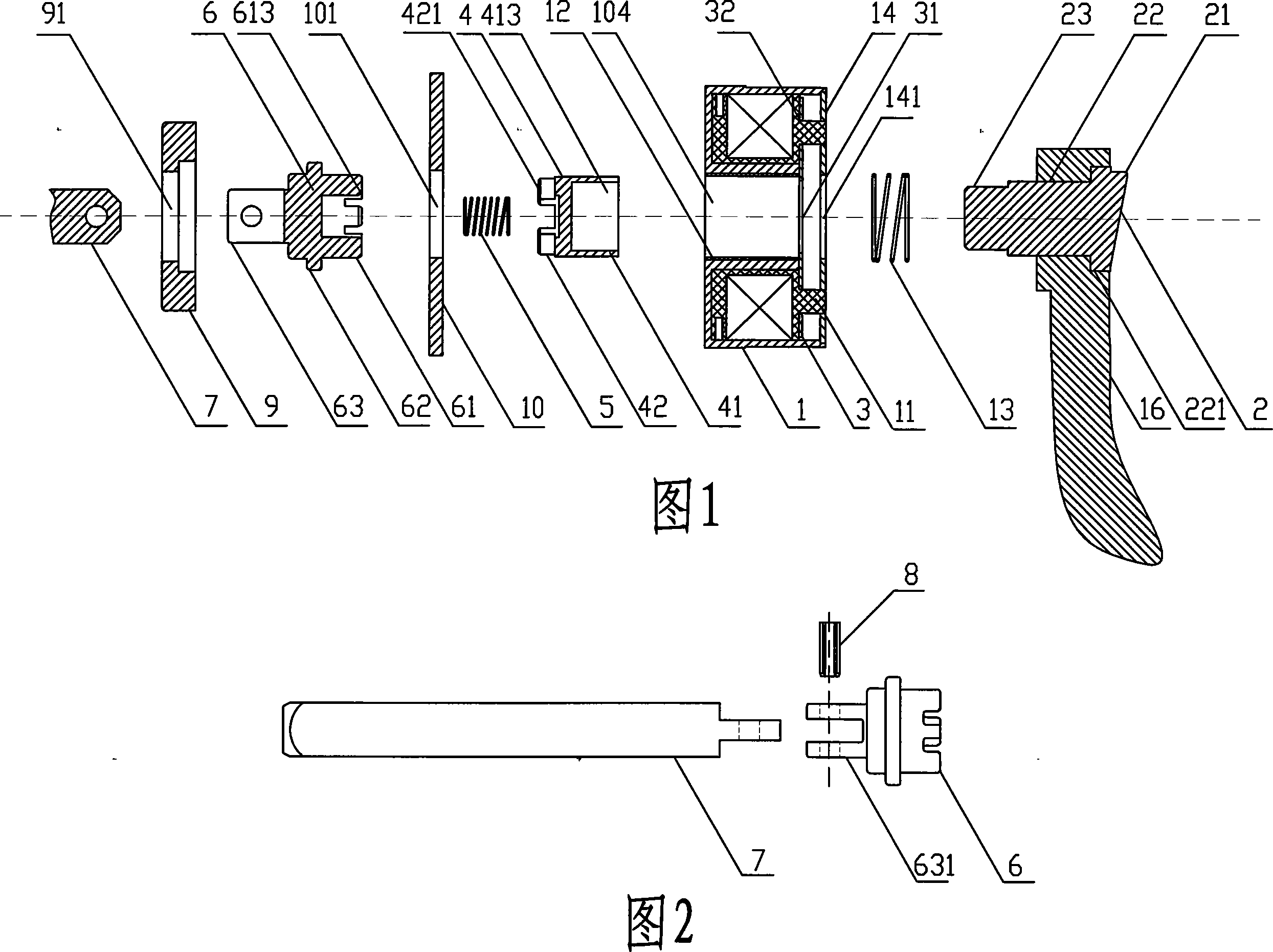
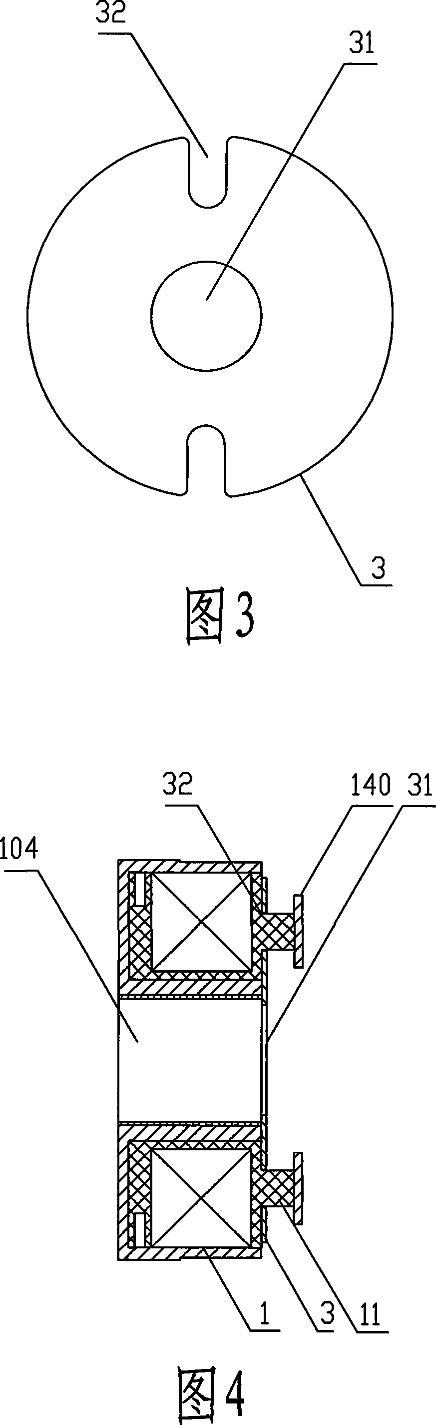
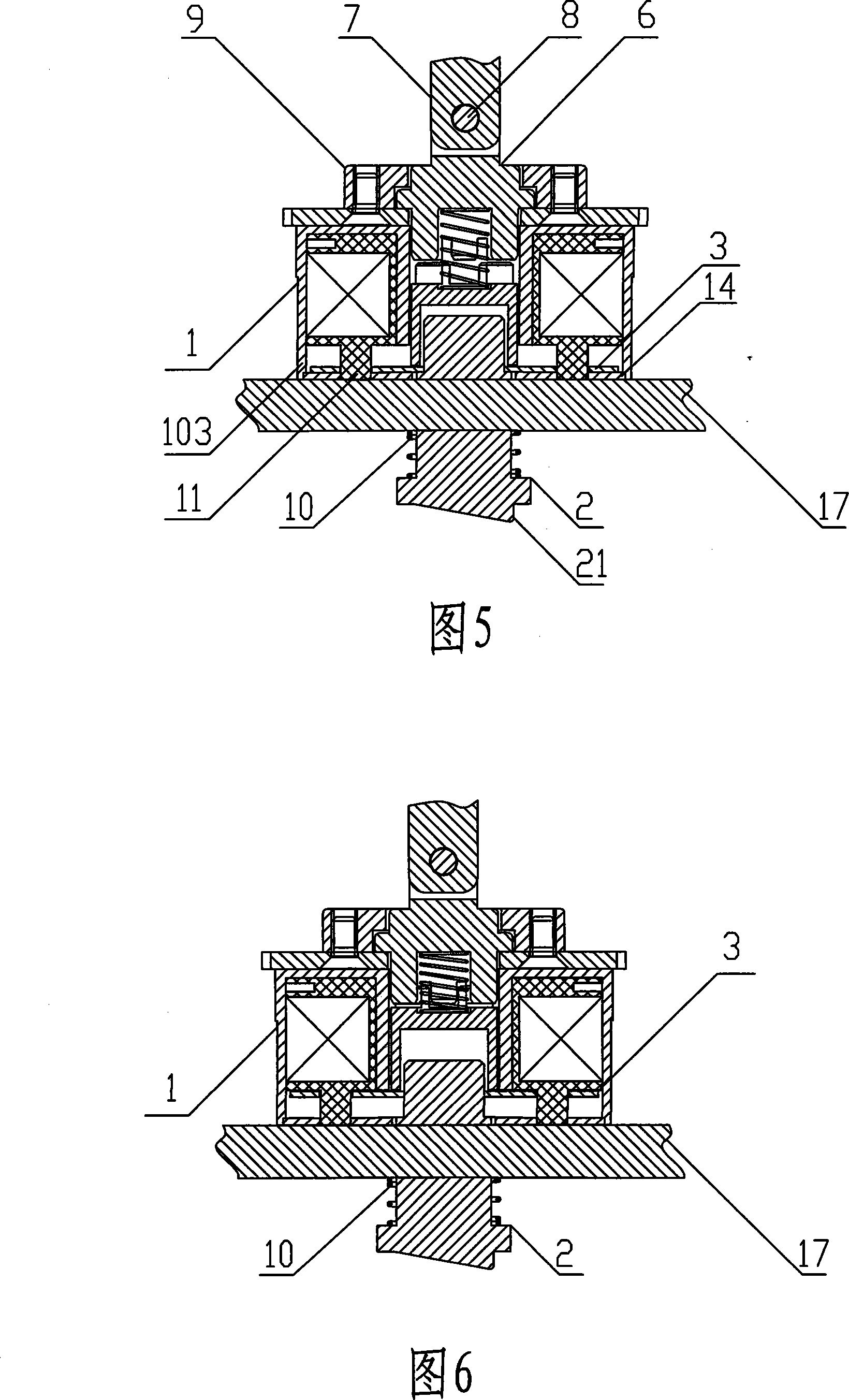
[0033] As shown in Fig. 1, Fig. 2 and Fig. 3, a clutch mechanism of an electromagnetic lock includes an electromagnet assembly 1, a pusher 2 sequentially connected front and back, a movable piece 3, a transmission part 4, a transmission part return spring 5 and a square Rod link block 6; also includes square bar 7 for driving the lock cylinder, bolt 8 connecting square bar link block 6 and square bar 7, fixed sleeve 9 for fixing square bar link block 6, fixed piece 10 and push piece Return spring 13. in:

[0034] As shown in Figure 1, the electromagnet assembly 1 is composed of a coil, a skeleton, and a casing surrounding the skeleton and the coil; force.

[0035] As shown in FIG. 1 , the pusher 2 is a part that is connected to the door handle 16 or the lock cylinder 15 to open the door lock, or is a rotating part that drives the door lock independently, and its tail end is coaxially connected with the transmission part 4 . As shown in Figure 1, the pusher 2 is composed of ...


PUM


Abstract

The clutch mechanism of the electromagnetic lock consists of an electromagnet assembly, a push piece connected in sequence, a push piece return spring, a movable piece, a transmission piece, a transmission piece return spring, a square bar linkage block, and a square bar. A sliding shaft and a stopper are arranged on the top end surface of the electromagnet assembly, and the stopper is fixedly connected with the sliding shaft; the movable piece is slidably sleeved on the sliding shaft; the head of the transmission part is provided with a first blind hole cavity; the pushing part The protruding part of the main body passes through the central hole of the movable piece and fits into the first blind hole cavity of the transmission part, and the square rod linkage block is movably connected with the square rod, which facilitates the replacement and folding of the square rod. The clutch mechanism is mainly used in a dual-purpose electromagnetic lock that can be opened and closed mechanically and controlled by an electric circuit.

Description

technical field [0001] The utility model relates to a clutch mechanism, more precisely a clutch mechanism of an electromagnetic lock. Background technique [0002] Chinese patent ZL01255674.2 discloses a lock core structure of an electromagnetic lock consisting of a rotating shaft, a buckle rod, an electromagnet coil, a long handle holder, and a long handle card connecting rod. The buckle rod is placed in the center hole of the electromagnet ring Inside, a spring is provided between the concave-convex groove of the shaft buckle on the left side of the electromagnet ring and the left buckle concave-convex groove of the buckle rod, and a positioning bump is arranged on the right end of the electromagnet ring, a large disc, and an anti-off piece The looper is on the positioning bump, and there is also a small disc between the large disc and the buckle rod. The right buckle concave-convex groove of the buckle rod corresponds to the handle long card connecting rod, and the handle...

Claims


Application Information

Patent Timeline
Patent Type & Authority Applications(China)
IPC IPC(8): E05B47/00E05B15/14F16D27/00
Inventor 曹湛斌陈秀彬
Owner GUANGDONG ARCHIE HARDWARE
Why Eureka
Try Eureka