Antisymmetric involute plastic gear

A technology of plastic gears and involutes, applied in belt/chain/gear, components with teeth, portable lifting devices, etc. Long wear life, good elasticity, low noise effect

Inactive Publication Date: 2008-05-21
TAIYUAN UNIV OF TECH
View PDF0 Cites 17 Cited by
  • Summary
  • Abstract
  • Description
  • Claims
  • Application Information

AI Technical Summary

Problems solved by technology

The main disadvantage of this kind of plastic gear is low load capacity, poor heat resistance, etc.
In order to improve the load-carrying capacity of plastic gears and reduce the operating temperature, the method of filler modification is often used, which is not only cumbersome and costly, but also brings so

Method used


Image

  • Antisymmetric involute plastic gear

Examples


Embodiment approach 1

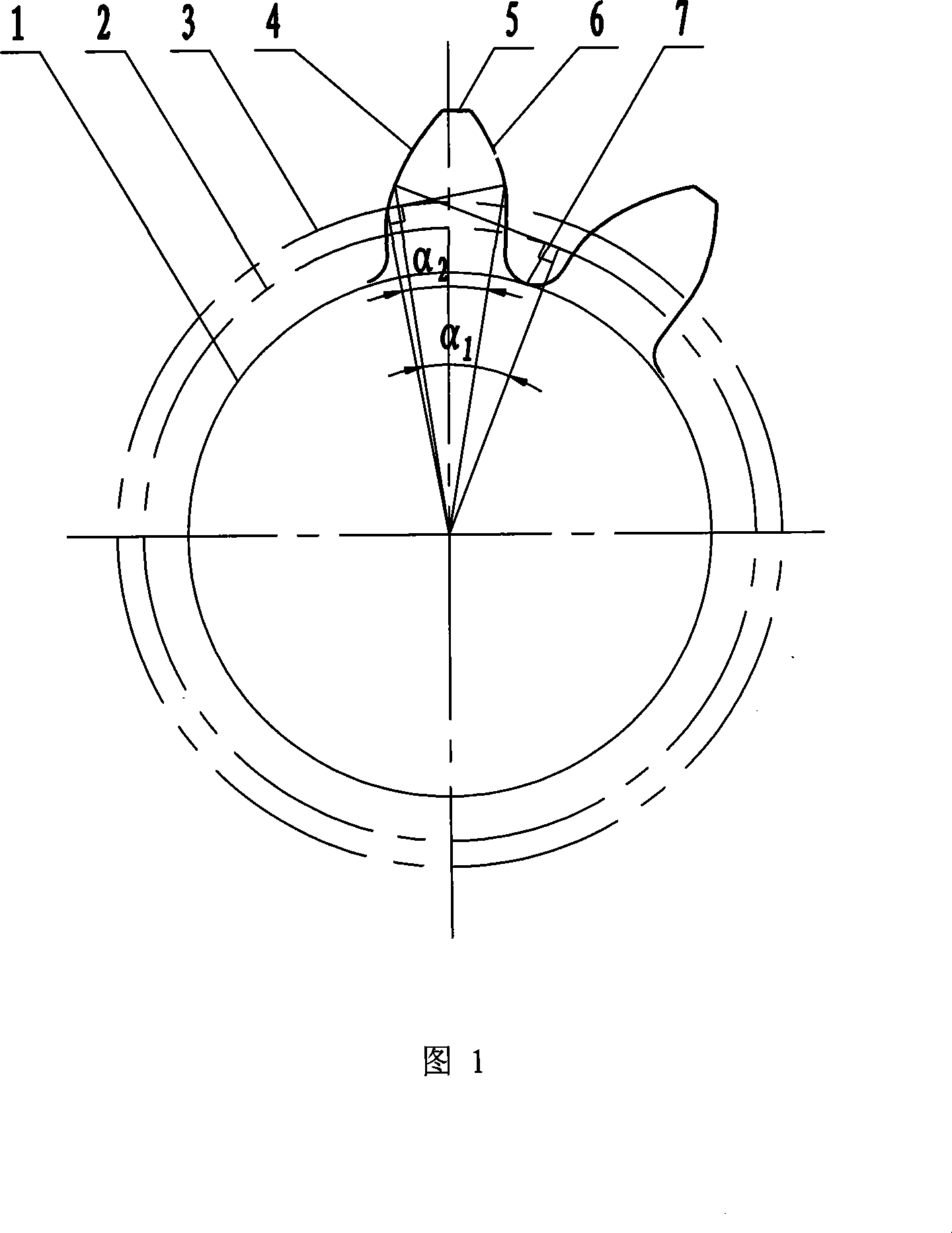
[0014] The tooth shape of the gear is a large pressure angle involute tooth profile 4 generated by the dedendum circle 1 and a small diameter base circle 2, a small pressure angle involute tooth profile 6 generated by a large diameter base circle 3, an addendum 5 and a transition Composed of curve 7.

[0015] for alpha 1 >α 2 Time:

[0016] by alpha 1 =15°, α 2 =14.5°, m=1.25, z=24, h a1 * = 1.0, h a2 * =0.95, c 1 * =0.35, c 2 * =0.4, m a = 0.4 / 24 = 0.0167.

[0017] got d b1 =mzcosα 1 =1.25×24cos15°=28.98(mm)

[0018] d b2 =mzcosα 2 =1.25×24cos14.5°=29.04(mm)

[0019] d a =(z+2h a1 * )m=(24+2×1)×1.25=32.5(mm)

[0020] S a = d b1 m a =28.98×0.0167=0.483966(mm)

[0021] d f =(z-2h a1 * -2c 1 * )m=(24-2×1-2×0.35)×1.25=26.625(mm)

[0022] According to the base circle diameter d b1 and d b2 For the same reference and opposite directions, the involute tooth profile 4 with a large pressure angle and the involute tooth profile 6 with a small pressure...

Embodiment approach 2

[0024] for alpha 1 >α 2 Time:

[0025] by alpha 1 =30°, α 2 =14.5°, m=1.25, z=24, h a1 * = 1.0, h a2 * =0.90, c1 * =0.3, c 2 * =0.4, m a =0.325 / 24=0.0135.

[0026] got d b1 =mzcosα 1 =1.25×24cos30°=25.98(mm)

[0027] d b2 =mzcosα 2 =1.25×24cos14.5°=29.04(mm)

[0028] d a =(z+2h a1 * )m=(24+2×1)×1.25=32.5(mm)

[0029] S a = d b1 m a =25.98×0.0135=0.35073(mm)

[0030] d f =(z-2h a1 * -2c 1 * )m=(24-2×1-2×0.3)×1.25=26.75(mm)

[0031] Diameter d at tooth top 5 a The arc length between the two involutes is 2.3364mm. Since the diameter d of the dedendum circle 1 f greater than the diameter d of the small diameter base circle 2 b1 , so the formed large pressure angle involute tooth profile 4 is completely involute; due to the diameter d of the dedendum circle 1 f smaller than the diameter d of the large diameter base circle 3 b2 , so the small pressure angle involute tooth profile 6 formed is divided into two parts: the involute between the large d...

Embodiment approach 3

[0033] for alpha 1 >α 2 Time:

[0034] by alpha 1 = 45°, α 2 =14.5°, m=1.25, z=24, h a1 * = 1.0, h a2 * = 1.0, c 1 * =0.45, c 2 * =0.45, m a =0.25 / 24=0.0104.

[0035] got d b1 =mzcosα 1 =1.25×24cos45°=21.21(mm)

[0036] d b2 =mzcosα 2 =1.25×24cos14.5°=29.04(mm)

[0037] d a =(z+2ha1 * )m=(24+2×1)×1.25=32.5(mm)

[0038] S a = d b1 m a =21.21×0.0104=0.220584(mm)

[0039] d f =(z-2h a1 * -2c 1 * )m=(24-2×1-2×0.45)×1.25=26.375(mm)

[0040] Diameter d at tooth top 5 a The arc length between the two involutes is 5.4899mm. Since the diameter d of the dedendum circle 1 f greater than the diameter d of the small diameter base circle 2 b1 , so the formed large pressure angle involute tooth profile 4 is completely involute; due to the diameter d of the dedendum circle 1 f smaller than the diameter d of the large diameter base circle 3 b2 , so the small pressure angle involute tooth profile 6 formed is divided into two parts: the involute between the la...


PUM


Abstract

The invention provides a dissymmetrical involute plastic gear, which belongs to the machine manufacturing field. The invention is characterized in that the technical proposal of the invention is that unsymmetrical involute profiles are adopted on both sides of the gear teeth of the plastic gear, the pressure angles on both sides of the gear teeth are unequal and the involute profile 4 of the larger pressure angle is taken as the working side; the tooth of the gear consists of a dedendum circle 1, the larger pressure angle involute profile 4 generated by a minor diameter base circle 2, the small pressure angle involute profile 6 generated by a major diameter base circle 3, a tooth top 5 and a transition curve 7. By comparing with the prior symmetrical involute plastic gear, the carrying capacity of the invention is improved, the service temperature is reduced and the service life is prolonged. Accordingly, the invention has wide application prospect and considerable economic benefits.

Description

technical field [0001] The invention relates to an asymmetric involute plastic gear, which belongs to the field of mechanical manufacturing, and specifically relates to a technical scheme in which an asymmetric involute tooth profile is adopted on both sides of the teeth of the plastic gear. Background technique [0002] Gear transmission is the most widely used transmission mode in mechanical transmission. Since the successful development of fiber nylon in 1935, the polymer synthetic material industry has developed rapidly, and plastics have been widely used as a new type of gear material. At present, the tooth shape of the plastic gear is symmetrical, and it is designed from the only pressure angle, that is, only one base circle. There are many standard tooth profiles, that is, the indexing circle pressure angle α = 20°, and the addendum height coefficient h a * =1 form; there are also non-standard tooth profiles (α>20°, h a * <1), for example α=25°, h a * = 0...

Claims


Application Information

Patent Timeline
IPC IPC(8): F16H55/17F16H55/08F16H55/06
Inventor 郝瑞贤李元宗李威陈新国
Owner TAIYUAN UNIV OF TECH
Why Eureka
Try Eureka