Pivot bearing device, particularly for a rotating circular table of a machine tool

A technology for rotating bearings and worktables, which can be used in rotating bearings, rolling contact bearings, linear bearings, etc., and can solve problems such as increased cost, maximum speed limit, structural and technical difficulties, etc.

Inactive Publication Date: 2008-05-21
SCHAEFFLER TECH AG & CO KG
View PDF0 Cites 24 Cited by
  • Summary
  • Abstract
  • Description
  • Claims
  • Application Information

AI Technical Summary

Problems solved by technology

This increases costs and sometimes presents construction-techni...

Method used


Image

  • Pivot bearing device, particularly for a rotating circular table of a machine tool
  • Pivot bearing device, particularly for a rotating circular table of a machine tool

Examples


Embodiment Construction

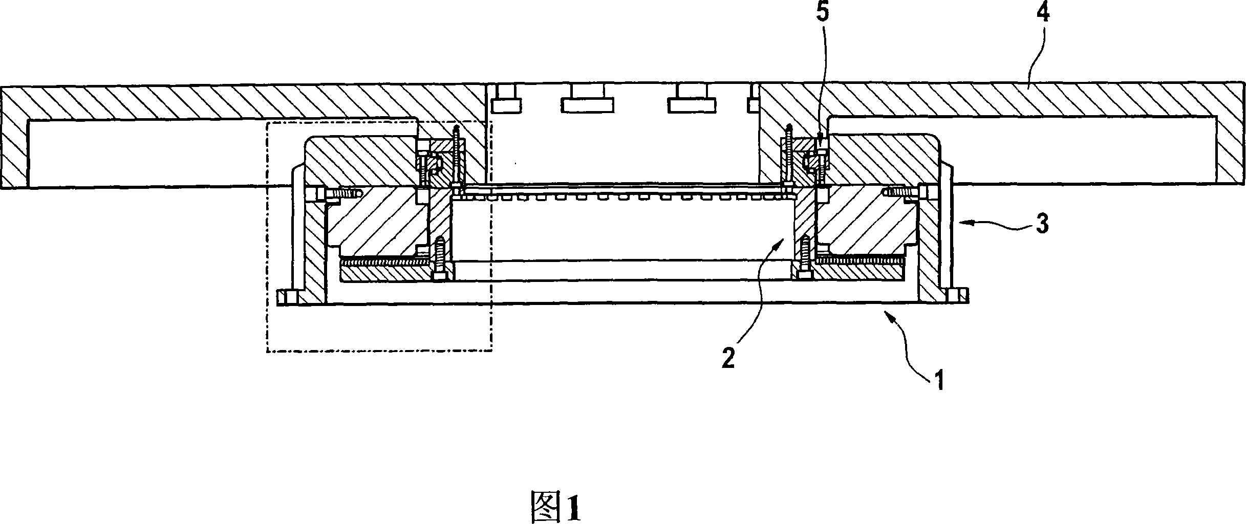
[0017] FIG. 1 shows a rotary bearing arrangement 1 according to the invention, which consists of a first arrangement part 2 which is rotatable in the installed state and a second arrangement part 3 which is held stationary during use. In the embodiment according to FIG. 1, a round table 4 is provided on the first device part, on which for example various tensioning devices can be arranged for holding workpieces or the like. The first device part 2 and the second device part 3 are rotationally connected to each other via a combined two-piece rolling bearing 5 , wherein the rolling bearing 5 consists of a radial bearing 6 and two axial bearings 7 . So also combined radial-axial cylindrical roller bearings are involved.

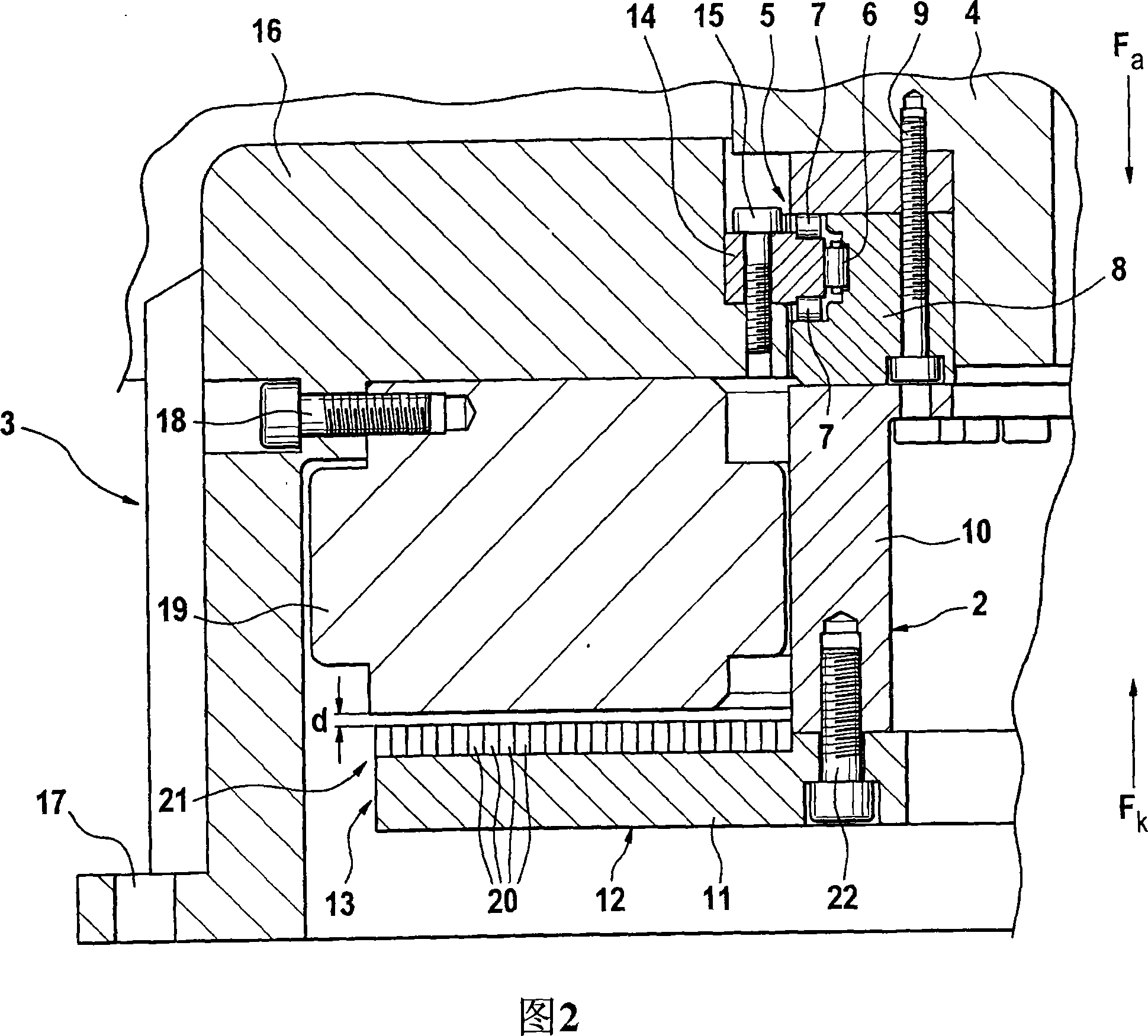
[0018] As further shown in FIG. 2 , on the one hand, the circular bearing table 4 is fixed on the inner ring-shaped bearing part 8 by a bolt connection 9 , and on the other hand, a center piece is provided across the middle piece 10 and fixed on the middle piece...


PUM


Abstract

A pivot bearing device, particularly for a rotating circular table of a machine tool is provided, and includes a first device part, which is to be connected to an element that is to be rotatably mounted, particularly to the circular table, and a second fixed device part. The device parts are connected via at least one antifriction bearing upon which an axial force acts. A magnet device ( 21 ), which acts between the first and second device parts ( 2, 3 ), is provided for generating a compensating force (Fk) oriented in essentially the opposite direction to the axial force (Fa).

Description

technical field [0001] The invention relates to a rotary bearing arrangement, in particular for a rotatable round table of a machine tool, which comprises a first device part which is connected to a rotatably mounted element, in particular a round table, the rotary bearing arrangement A second device part is also contained which remains fixed, and said two device parts are connected by at least one rolling bearing on which axial forces act. Background technique [0002] The function of a rotary bearing arrangement is generally to allow a first element to be rotatably supported relative to a second element which remains fixed. As an example, a machine tool with a rotatable circular table is cited and said circular table is held rotatably relative to a machine frame or the like via a rotary bearing arrangement. Known swivel bearing arrangements comprise a first device part coupled to a rotatably mounted element, such as a circular table, and a second device part which remains...

Claims


Application Information

Patent Timeline
IPC IPC(8): B23Q1/52F16C29/06
CPCF16C39/063F16C2300/14F16C19/381B23Q2220/004F16C2322/39B23Q1/522B23Q2210/004B23Q1/52F16C29/06
Inventor 理查德·内格莱托马斯·迪滕霍费尔马丁·施赖伯
Owner SCHAEFFLER TECH AG & CO KG
Why Eureka
Try Eureka