Supercharge Your Innovation With Domain-Expert AI Agents!

Concrete pedestal pile construction equipment and its construction method

A technology of construction equipment and construction methods, applied in sheet pile walls, foundation structure engineering, construction, etc., can solve problems such as broken piles, large side wall friction, necking, etc., to achieve improved work efficiency, reduced soil squeezing effect, and reduced The effect of friction

Inactive Publication Date: 2008-05-28
高世科
View PDF1 Cites 7 Cited by
  • Summary
  • Abstract
  • Description
  • Claims
  • Application Information

AI Technical Summary

Problems solved by technology

When the pile diameter is large or the foundation soil layer is relatively hard (such as hard plastic clay or fully weathered bedrock), the side wall friction force on the casing is relatively large, so it is difficult to sink the casing to a predetermined depth or from the specified depth. The location is proposed, and the construction quality and work efficiency are affected
In addition, this method often causes adjacent piles to float up or break piles, necking and other pile body defects due to the soil squeezing effect when the casing is sunk.

Method used


Image

  • Concrete pedestal pile construction equipment and its construction method
  • Concrete pedestal pile construction equipment and its construction method

Examples


Embodiment 1

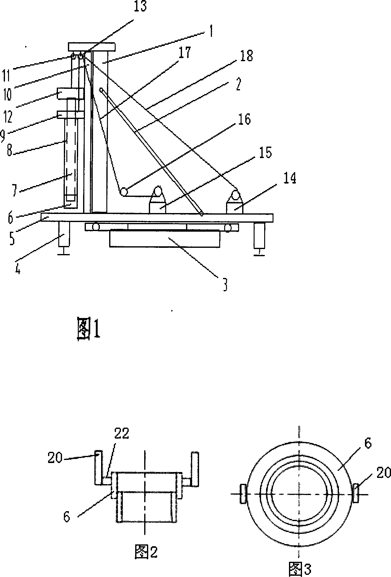
[0046] As shown in Figure 1, a construction equipment for concrete bottom expansion piles includes a chassis girder 5 with four telescopic hydraulic outriggers 4 and a running mechanism 3 at the bottom, and the front end of the chassis girder 5 is fixedly connected with a vertical guide rail The main frame 1 of 10, the main frame 1 is supported and connected to the chassis girder 5 by two diagonal braces 2, and the other ends of the diagonal braces 2 are respectively connected to different positions on the chassis girder, and the two diagonal braces 2 are connected to the main frame The connection with the chassis girder forms a three-point support structure. The beam of the main frame 1 is provided with a pulley block, and the chassis girder 5 is fixedly connected with a main hoist and an auxiliary hoist. The steel rope 2 17 protruding from the auxiliary hoist 15 bypasses the auxiliary After the pulley 16 goes around the auxiliary pulley 13 of the pulley block, it is connected...

Embodiment 2

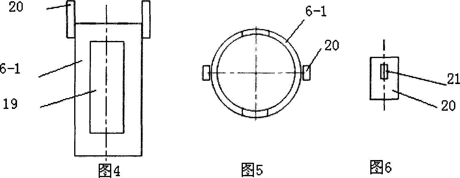
[0060] As shown in Fig. 1 and Fig. 4 to Fig. 6, a kind of construction equipment of concrete bottom expansion pile, earth taker adopts lateral through-hole type earth taker 6-1, and the lower end of casing 8 is equipped with take-off lug 20 The earthenware 6-1 connects the earthenware 6-1 with the casing 8 through the elongated hole 21 on the lifting lug 20 and the corresponding connection hole on the casing 8 with screws, and the earthenware is provided with a digging on the pipe wall. The tubular structure of soil hole 19, other structures are with embodiment 1. For relatively loose soil layer, should use the lateral through-hole type soil fetcher of this embodiment.

[0061] Utilize the construction method of the concrete expanded bottom pile of the construction equipment of above-mentioned concrete expanded bottom pile, comprise the steps:

[0062] a) Stand the casing with a special earth picker at the bottom on the foundation surface of the specified pile position in the...


PUM


Abstract

The invention discloses a concrete club-footed pile construction device and a construction method, which belongs to the technical field of concrete caisson pile construction, wherein the construction device comprises a chassis girder and a main shelf whose front end is fixedly connected with a vertical guide rail. The main shelf is provided with a pulley group, and a steel rope is connected with a protecting barrel after bypassing a secondary pulley, which is connected with a pillar hammer after bypassing a main pulley of the pulley group, the pillar hammer is positioned in the protecting barrel whose lower end is provided with an earth-fetching device and the top end is fixedly connected with a vibration impact hammer. The construction method is that earth is firstly fetched to form a pile hole, and the protecting barrel is sunken, and a pile base which is finally formed belongs to an earth-squeezing or half earth-squeezing pile. The invention can easily sink the protecting barrel to the pre-determined depth or raise the protecting barrel from a formulated position, and the work efficiency can be improved, and the shortcomings that the adjacent pile body floats upwards or is broken or the neck of the pile body shrinks which is caused by earth-squeezing effect when the protecting barrel is sunken are avoided, and the construction quality can be guaranteed.

Description

technical field [0001] The invention relates to a construction device and a construction method of a concrete bottom expansion pile. Background technique [0002] Concrete cast-in-situ piles are often used in the foundation construction of buildings. A construction method of this pile is to use a casing and a column hammer for construction, such as the method disclosed in the invention patent specification with the notification number CN1093582C, that is, by using a column hammer to tamp Hitting the casing or tamping the soil inside the casing makes the casing sink to a predetermined depth, thereby forming a pile hole, and then forming a tamping head at the pile end through a column hammer, pouring concrete for the pile body while lifting the casing, thereby Form the entire concrete pouring pile. When the pile diameter is large or the foundation soil layer is relatively hard (such as hard plastic clay or fully weathered bedrock), the side wall friction force on the casing i...

Claims


Application Information

Patent Timeline
IPC IPC(8): E02D11/00E02D5/44
Inventor 高世科梁勇彭昌福高世权
Owner 高世科
Features
  • R&D
  • Intellectual Property
  • Life Sciences
  • Materials
  • Tech Scout
  • Unparalleled Data Quality
  • Higher Quality Content
  • 60% Fewer Hallucinations
Learn More