Non-dredging guiding driller dynamic head main spindle

A drilling rig power head and non-excavation technology, which is applied in the direction of rotary drilling rigs, drill pipes, drill pipes, etc., can solve the problems of easy damage of output joints, drill pipe buckles, cumbersome operation, and increased fault points, so as to avoid mutual interference , Micro-motion operation freely, guarantee the effect of coaxiality

Inactive Publication Date: 2008-05-28
LIANYUNGANG HUANGHAI MACHINERY
View PDF0 Cites 17 Cited by
  • Summary
  • Abstract
  • Description
  • Claims
  • Application Information

AI Technical Summary

Problems solved by technology

The disadvantages of the above-mentioned floating structure of the power head are: ①The floating structure is set at the relative position between the power head box and the carriage, and the joystick moves the carriage to drive the movement of the power head. When loading and unloading drill pipes, the carriage must be moved first Only when the power head floats in the opposite direction can there be a floating function. The operation is cumbersome, and it is easy to reverse, resulting in misoperation, causing the drill pipe threaded buckle, the spindle system, and the rigid parts of the carriage system to be overloaded and damaged.
②The guide surface has a large gap and swings from side to side, which is easy to cause misalignment, resulting in the output joint not being able to fit the drill pipe when making up the drill pipe, and human inter

Method used


Image

  • Non-dredging guiding driller dynamic head main spindle

Examples


Embodiment Construction

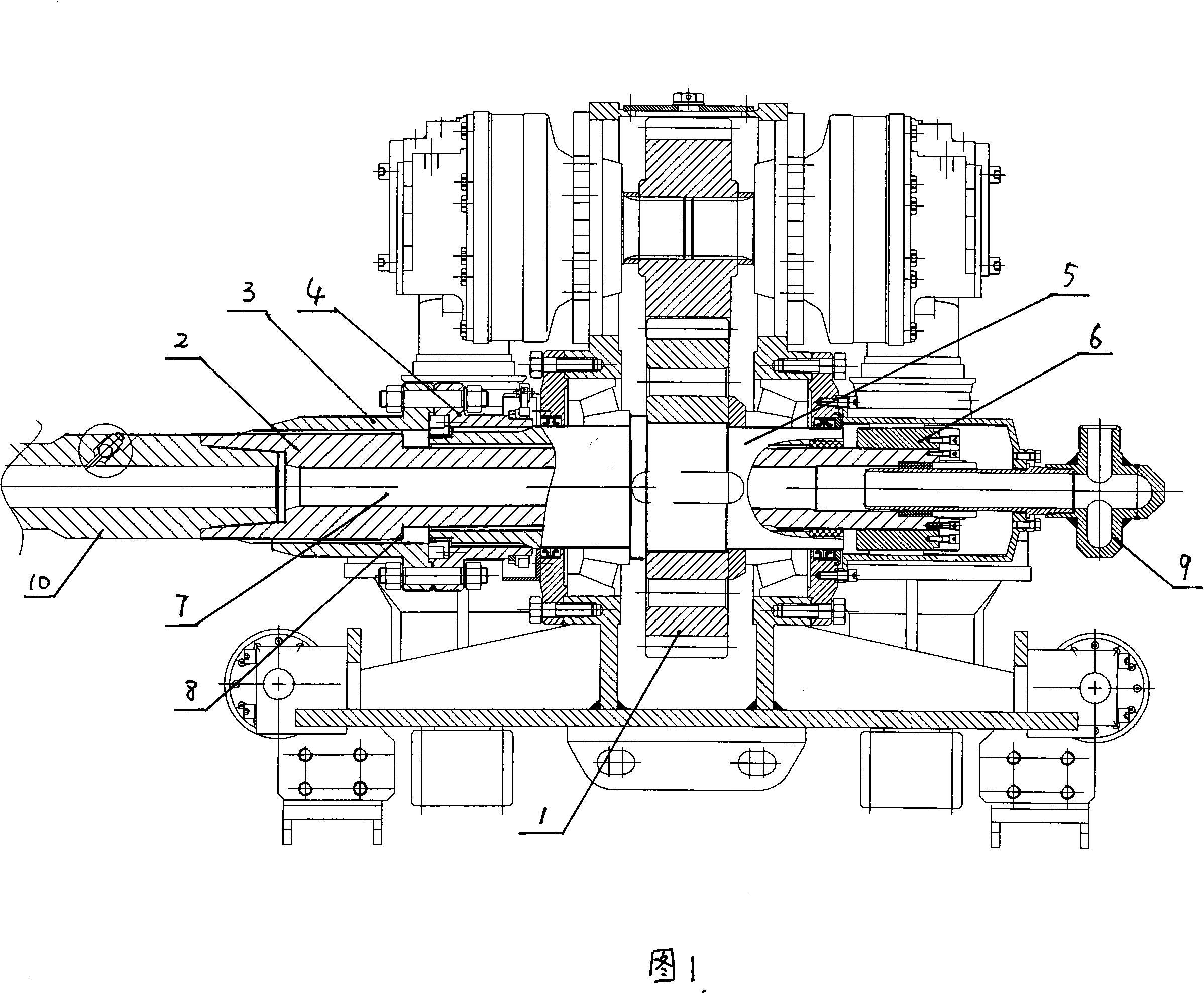
[0015] A main shaft of a power head of a non-excavation steerable drilling machine includes a transmission sleeve 5, a floating mandrel 2, a torsion transmission spline sleeve 3 and a floating distance limiting mechanism.

[0016] The transmission gear 1 is fixed in the middle of the transmission sleeve 5 so as to be connected with the transmission system; the floating mandrel 2 is set in the transmission sleeve 5 and is slidably matched with the inner hole of the transmission sleeve 5, and the center of the floating mandrel 2 is provided with mud running up and down The through hole 7; the bottom end of the floating mandrel 2 is provided with an interface connecting the vulnerable short joint 10, and the upper end of the floating mandrel 2 is provided with a mud mixing introduction joint 9. The torsion transmission spline sleeve 3 is fixed and rigidly connected to the bottom of the above-mentioned transmission sleeve 5, and the torsion transmission spline sleeve 3 cooperates w...


PUM


Abstract

A main shaft of a motor head of a no dig guiding driller comprises a driving sleeve which is butt jointed with a driving system, a floating core shaft which is arranged in the driving sleeve, which is slideably matched with an inner hole of the driving sleeve, a transmission torsion splined hub which is fixedly and hard connected with the bottom of the driving sleeve, the transmission torsion splined hub is engaged with an outer spline on the lower portion of the floating core shaft to transmit torque, meanwhile the corn shaft achieves upper and lower floating along the spline, and a floating distance limiting mechanism is arranged between the floating core shaft and the driving sleeve. The torque is transferred to the floating core shaft through an output flange and the transmission torsion splined hub by adopting a core shaft floating way, the return rotating of a drilling tool is achieved by a drill rod of a damageable short segment of the floating core shaft, the core shaft which has no middle transmission step can directly float, and the floating range is bigger than a traditional motor head floating way, the motor head which is fed or back dragged can stay on any position to guarantee the reliability of floating. Centring accuracy is high, a main shaft is not suppressed when the drill rod is detached, and the main shaft is easy to be centered when the drill rod is mounted.

Description

technical field [0001] The invention relates to a non-excavation guiding drilling machine, in particular to a main shaft of a power head of the non-excavating guiding drilling machine. Background technique [0002] On the one hand, the power head of the non-excavation directional drilling rig transmits the rotary motion of the hydraulic motor to the main shaft through the reduction mechanism, so that the shaft drives the drill pipe and the drilling tool to rotate with the rated torque, and plays the role of cutting and cutting to make circular cross-section holes. Function; on the other hand, the force of the feeding device is applied to the power head box, the main shaft bearing and the main shaft through the transmission device, and through the forward and backward movement of the power head, it finally drives the drill pipe mounted on the main shaft and can rotate with the main shaft The drilling tool advances or retreats, so that the circular cross-...

Claims


Application Information

Patent Timeline
IPC IPC(8): E21B3/02E21B17/00
Inventor 马松岭文治国杨东明周亚军
Owner LIANYUNGANG HUANGHAI MACHINERY
Why Eureka
Try Eureka