A permanent magnetic mechanism

A permanent magnet mechanism, permanent magnet technology, applied in electromagnetic relays, electromagnetic relay details, high-voltage air circuit breakers, etc., can solve the problem of limited power and structural space of closing coils, inability to design electromagnetic coils, and burning of closing coils and other problems, to achieve the effect of simple structure, reliable performance and increased space

Inactive Publication Date: 2008-05-28
杨永平 +1
View PDF1 Cites 13 Cited by
  • Summary
  • Abstract
  • Description
  • Claims
  • Application Information

AI Technical Summary

Problems solved by technology

Since the closing electromagnetic coil and the opening electromagnetic coil are used in the upper and lower parts of the permanent magnet circuit breaker, the design of the closing coil is mostly instantaneous operation, which limits the power supply and structural space of the closing coil, and the closing coil produces the same Under the premise of electromagnetic strength, it is impossible to design long-term working electromagnetic coils
In this way, it often happens that the closing coil is burned under frequent operation or certain faults, especially in the case of mine explosion-proof, which has a great impact on normal production.

Method used


Image

  • A permanent magnetic mechanism

Examples


Embodiment Construction

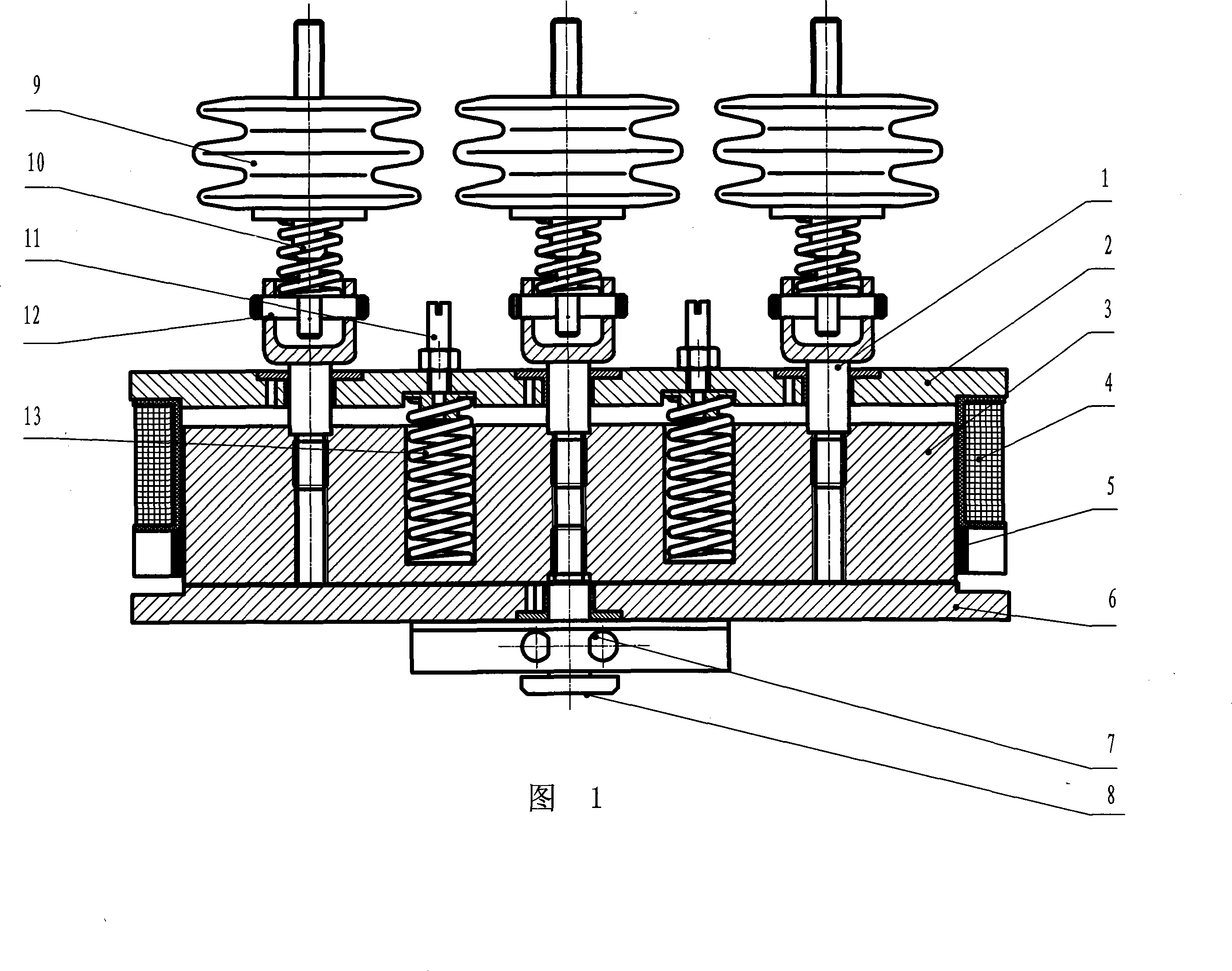
[0010] As shown in the figure, the present invention includes an upper casing 2 and a lower casing 6, and a strip-shaped moving iron core 3 is arranged inside the upper casing 2 and the lower casing 6, and three upper guides are fixed on the upper part of the moving iron core 3. The rod 1 and the upper guide rod 1 pass through the upper housing 2; two opening springs 13 are symmetrically arranged on both sides of the upper guide rod 1 located in the middle on the moving iron core 3, and the upper end of the opening spring 13 is connected with a opening spring The top wire 11, the opening spring 13 can be adjusted and locked through the top wire 11 of the opening spring; the closing coil 4 is set on the moving iron core 3, and the permanent magnet 5 is installed under the closing coil 4, and the permanent magnet mechanism is composed of the above basic components. An insulator 9 and a contact spring 10 are installed on the upper guide rod 1 through a pin shaft 12, and a lower g...


PUM


Abstract

The invention relates to a permanent magnetism mechanism, which comprises an upper case body and a lower case body, wherein, a movable core is arranged between the upper case body and the lower case body; the upper part of the movable core is provided with three upper guide levers. Both sides of the upper guide lever positioned at the middle are provided with a tripping spring and a tripping spring adjusting screw. The upper part of the upper guide lever is provided with an insulator and a contact spring. The position where the lower part of the movable core corresponds to the upper guide lever is provided with a hand trip gear, and both sides of the movable core are provided with a closing coil and a permanent magnet. The invention has the advantages that linear drive is realized on a three step switch tube and the synchronicity and the operability of the three step action are more reliable; the adjustment of the speed of a trip also can be realized; the structure is simple; the cost is low. The invention can be widely used for a breaker and a contactor of a mine feed system, and the environment of the mine feed system is vile, and the mine feed system has high requirement for the reliability. Because the invention only adopts one closing coil, the space of the closing coil is increased. The number of turns of the closing coil can be increased on the premise that the coil diameter is the same or greater than the diameter of the primary coil. The invention can realize frequent electrification for a long time and can not be burnt under the condition that ampere-turn is invariable or the ampere-turn is properly enhanced.

Description

technical field [0001] The invention relates to a single-coil permanent magnet mechanism which is used in high, medium and low voltage circuit breakers and contactors in power systems and is linearly driven by the same moving iron core and multiple switch tubes. technical background [0002] At present, the permanent magnet mechanisms used in high, medium and low voltage circuit breakers and contactors in the power system are generally driven by a permanent magnet mechanism for each switch tube and synchronously controlled by electronic technology, or realized by a permanent magnet mechanism by turning the crank arm. Synchronously drive multiple switch tubes. The former is technically difficult and immature, and cannot be applied in occasions where the product price is low; the latter needs to add a guide device to realize linear drive, which not only has a complex structure, but also has a large energy loss, and its working reliability and stability are far inferior to Lin...

Claims


Application Information

Patent Timeline
Patent Type & Authority Applications(China)
IPC IPC(8): H01H3/28H01H33/38H01H50/42
Inventor 刘向昕陈子春杨文忠杨永平刘志平李再发张文英姜悦
Owner 杨永平
Why Eureka
Try Eureka