
Flat small digital TV antenna

A digital TV antenna and digital TV signal technology, applied in antenna, antenna array, resonant antenna, etc., can solve the problems of narrow bandwidth and poor electromagnetic wave efficiency

Active Publication Date: 2008-05-28
WISTRON NEWEB
View PDF4 Cites 0 Cited by
  • Summary
  • Abstract
  • Description
  • Claims
  • Application Information

AI Technical Summary

Problems solved by technology

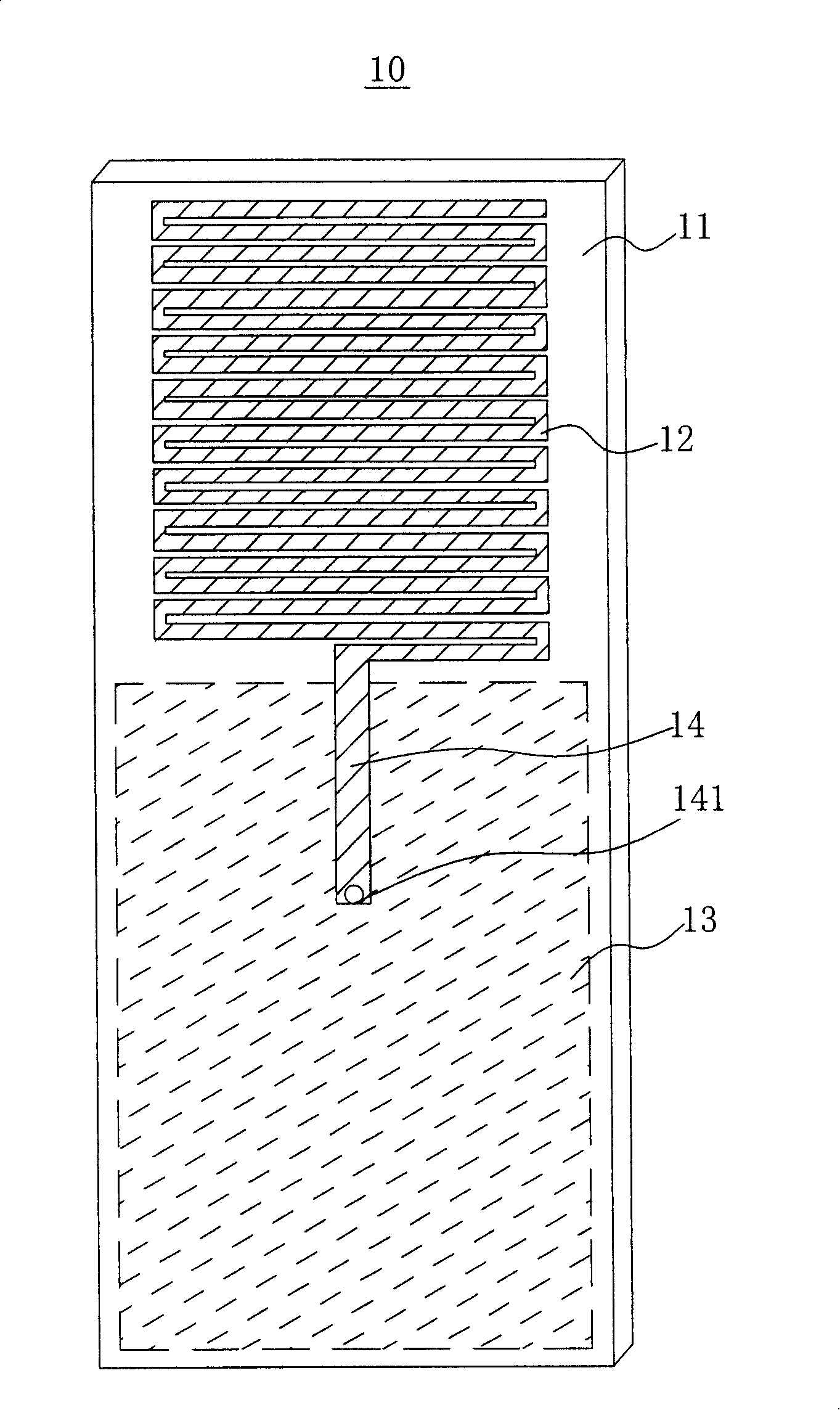
[0006] Although the above-mentioned antenna 10 can meet the requirement of miniaturization, its bandwidth (Bandwidth) is relatively narrow, and the efficiency of transmitting electromagnetic waves is relatively poor.

Method used


Image

  • Flat small digital TV antenna
  • Flat small digital TV antenna
  • Flat small digital TV antenna

Examples


Embodiment Construction

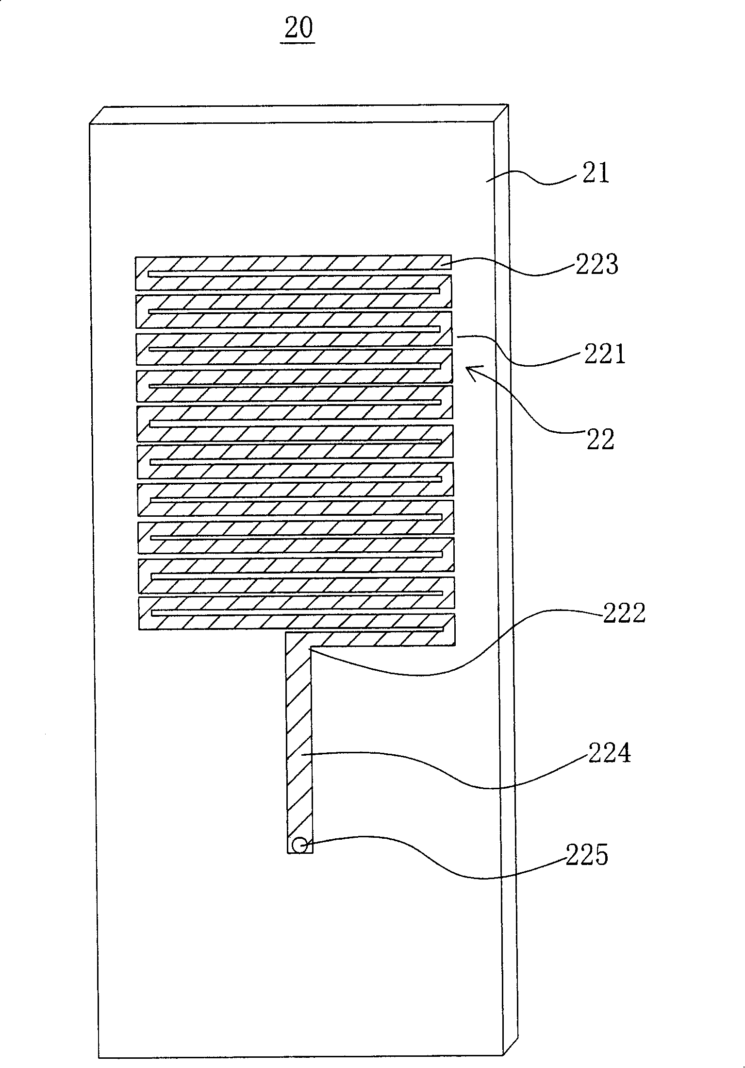
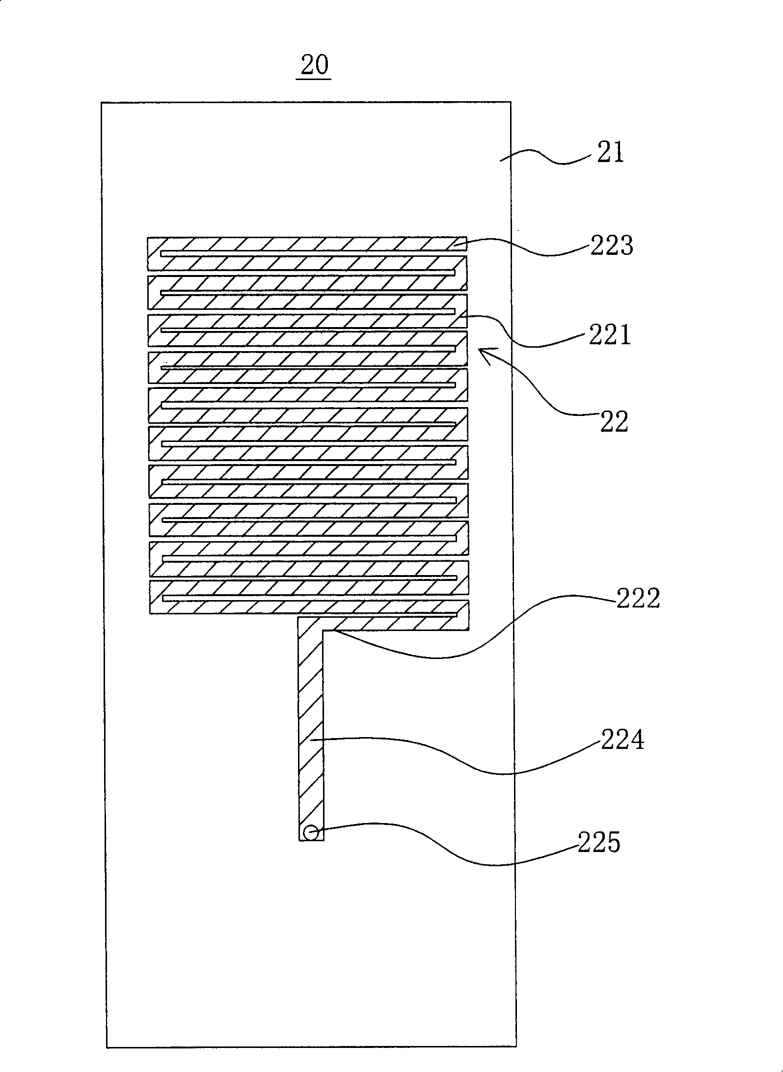
[0025] see figure 2 , 3A , as shown in 3B. The flat-panel small digital TV antenna of the present invention is used to combine with portable electronic devices such as mobile phones, notebook computers, personal digital assistants, etc., so as to improve the efficiency of transmitting digital TV signals by the antenna. The antenna 20 of the first embodiment of the present invention includes:

[0026] An insulating plate 21 can be made of general circuit board material;

[0027] A metal radiator 22 for the antenna 20 to receive / radiate electromagnetic wave signals; the metal radiator 22 is combined with the first surface of the insulating plate 21; the metal radiator 22 includes a meander portion 221, and the meander portion 221 has a first end 222 and The second end 223; the first end 222 is connected to a microstrip line 224, and the end point of the microstrip line 224 is used as the feeding point 225, such as Figure 3A shown;

[0028] A grounding metal piece 23 is us...


PUM


Abstract

The invention relates to a flat plate type miniature digital TV antenna which comprises a metal radiator which is the first surface binding of an insulating plate and a grounding metal element and a metal parasitic element which are connected with a second surface binding. The metal radiator is provided with a meandering curve part, the metal parasitic element is also provided with a meandering curve part corresponding to the position of the metal radiator, and the metal parasitic element increases the frequency width of an antenna receiver / radiation electromagnetic wave signal for promoting the efficiency of the digital TV signal.

Description

【Technical field】 [0001] The present invention relates to antennas for portable electronic devices such as mobile phones, notebook computers, and personal digital assistants, especially for receiving digital television antennas. 【Background technique】 [0002] There are a variety of antennas for receiving digital television signals, such as those disclosed in U.S. Patents U.S. 6,819,297, U.S. 6,639,555, U.S. 6,259,416, and Taiwan Patent No. I255589, No. I240451, No. M285154, and Taiwan Patent Publication No. 521455. [0003] Among them, Taiwan Patent Announcement No. 521455 discloses a planar miniaturized antenna for digital TV, including: a substrate, the upper and lower surfaces of which are respectively printed with copper foil to form a strip line; and a plurality of antennas, which are printed with copper foil The method forms Rampart Lines, which are respectively arranged parallel to the upper and lower surfaces of the substrate, cross-connected to the strip lines, and...

Claims


Application Information

Patent Timeline
IPC IPC(8): H01Q9/30H01Q9/40H01Q1/38H01Q13/00H01Q21/00
Inventor 陈志龙曾冠学黄俊铭
Owner WISTRON NEWEB
Learn More