
UPS power central power supply system and its method

A technology of centralized power supply and power supply, which is applied in general control systems, battery circuit devices, control/regulation systems, etc., can solve the problems of unreasonable distribution and utilization of UPS power, and achieve the effect of improving use efficiency

Inactive Publication Date: 2008-05-28
DELTA GREENTECH CHINA CO LTD
View PDF0 Cites 12 Cited by
  • Summary
  • Abstract
  • Description
  • Claims
  • Application Information

AI Technical Summary

Problems solved by technology

[0003] The technical problem to be solved by the present invention is to provide a UPS power supply centralized power supply system and its method, which can solve the problem that UPS power cannot be reasonably distributed and utilized in the existing power supply mode

Method used


Image

  • UPS power central power supply system and its method
  • UPS power central power supply system and its method
  • UPS power central power supply system and its method

Examples


Embodiment

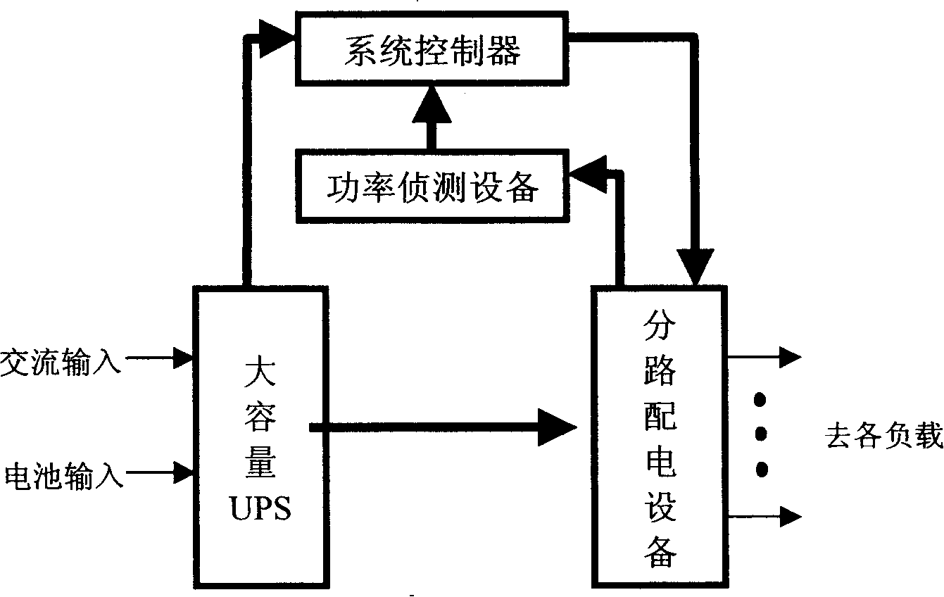
[0014] like figure 1 Shown is a schematic diagram of a specific embodiment of the present invention.

[0015] In this embodiment, the UPS power supply system includes: a large-capacity power supply UPS, branch power distribution equipment, power detection equipment, and a system controller. Wherein: large-capacity UPS is the provider of whole UPS power supply system energy, and its energy source is AC power supply and backup battery; For ease of understanding the present invention, Figure 4 A schematic diagram of the internal structure of the above-mentioned large-capacity UPS is provided. Since it is a prior art, the present invention does not specifically introduce the details in the figure; the large-capacity power supply UPS is also connected to the shunt power distribution equipment, and the actual backup The capacity is reported to the system controller in real time; the shunt power distribution equipment is connected to multiple user loads, and the wiring of different...


PUM


Abstract

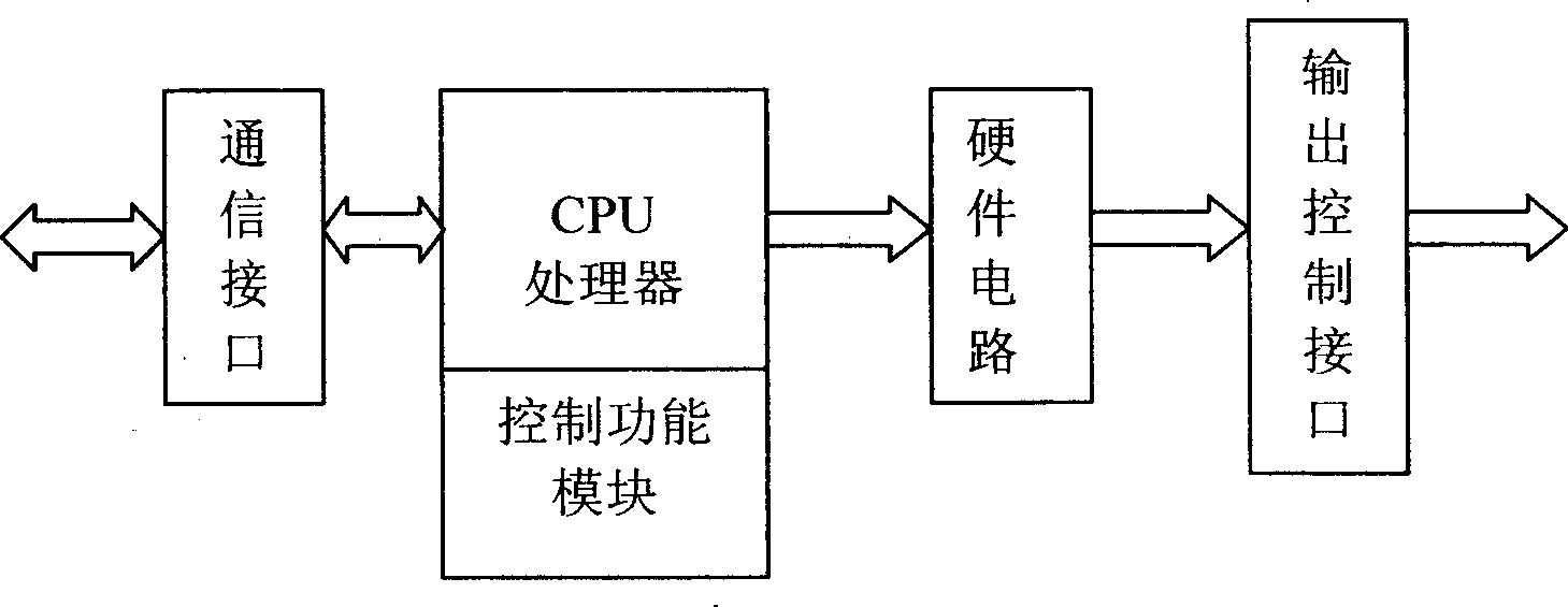
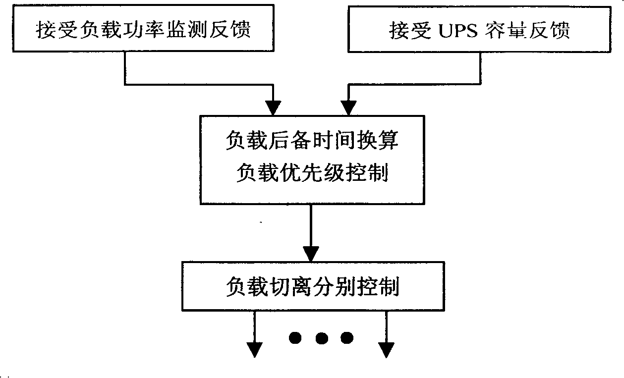
The invention relates to a UPS central power supply system and the method thereof. The system comprises a power supply system UPS with large capacity, a shunt distribution device, a plurality of power detection devices, and a system controller at least. The system controller comprises a communication interface, a hard ware circuit, a CPU processor, an output control interface and a control module. If a plurality of control systems are provided, the systems are connected in parallel and can be in backup mutually. The system controller in the method is connected with the practical reserve capacity of the power supply system UPS with large capacity and a plurality of loads with different power to calculate out the prepare time T1 of every load. Because the invention overcomes the problems in the design and the use method of the UPS system that the prepare time of the prior UPS power can not be adjusted and the energy of the UPS can not be dispensed, the invention can solve the problem that the UPS energy in the prior power supply can not be distributed and utilized reasonably.

Description

technical field [0001] The invention relates to a UPS power supply system, in particular to a centralized UPS power supply system and a method thereof. Background technique [0002] At present, the vast majority of UPS power supply systems are decentralized and controlled, and there are very few that use centralized power supply. However, whether it is distributed power supply or centralized power supply, the capacity and backup time allocated to different loads by the existing UPS power supply system are fixed, which causes when the actual power of different loads changes or due to UPS backup When the capacity changes, the backup time of the load cannot be effectively controlled, and the power adjustment cannot be performed, resulting in waste of power and greatly reducing the efficiency of the UPS. Contents of the invention [0003] The technical problem to be solved by the present invention is to provide a centralized UPS power supply system and its method, which can s...

Claims


Application Information

Patent Timeline
IPC IPC(8): H02J7/00G05B19/04G05B15/02
Inventor 李久宏张一
Owner DELTA GREENTECH CHINA CO LTD
Learn More