
Dual paraboloid reflector and dual ellipsoid reflector systems with optimized magnification

A reflector and second reflector technology, applied in the field of systems for collecting and concentrating electromagnetic radiation, can solve problems such as unfavorable aberrations, brightness, loss, and undescribed, and achieve the effect of reducing Fresnel reflection loss

Inactive Publication Date: 2010-05-26
WAVIEN
View PDF14 Cites 0 Cited by
  • Summary
  • Abstract
  • Description
  • Claims
  • Application Information

AI Technical Summary

Problems solved by technology

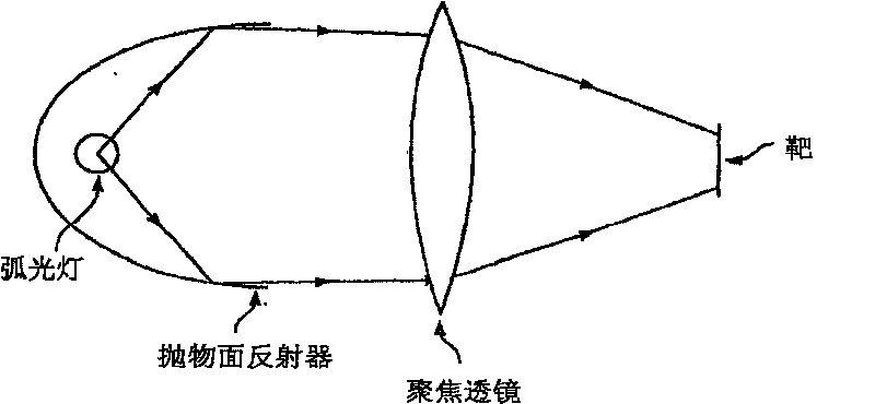
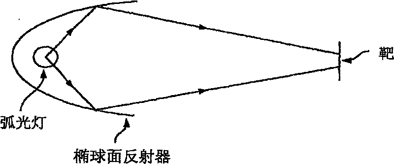
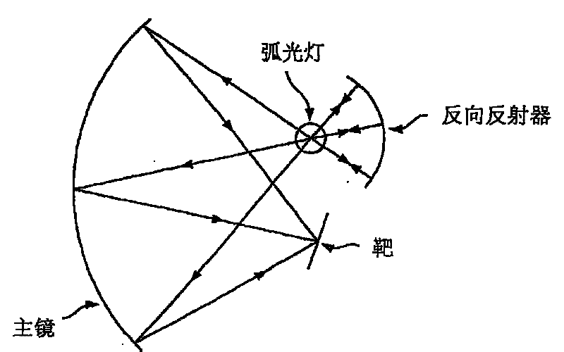
In particular, large divergence angles lead to the fact that light energy transmitted along a path similar to ray a will cover a relatively large area on the second parabolic reflector, resulting in unfavorable aberrations and loss of brightness
However, none of the references mentioned above describe a system capable of handling large angular divergences and optimizing the magnification between the source and the focused image to obtain maximum flux density at the target with minimum distortion

Method used


Image

  • Dual paraboloid reflector and dual ellipsoid reflector systems with optimized magnification
  • Dual paraboloid reflector and dual ellipsoid reflector systems with optimized magnification
  • Dual paraboloid reflector and dual ellipsoid reflector systems with optimized magnification

Examples


Embodiment Construction

[0043] Exemplary embodiments of the present invention are described below with reference to the accompanying drawings. These examples are only used to explain the principle of the present invention, and should not be construed as limiting the scope of the present invention.

[0044] refer to Figure 5 to Figure 6 and Figure 8 to Figure 10 , these figures show a typical exemplary embodiment of the present invention, the present invention is related to the following four main components: electromagnetic radiation source 10, first reflector 20, second reflector 30 and target or tapered light pipe (TLP) 50 .

[0045] Preferably, the electromagnetic radiation source 10 is a light source with a glass bulb 12 . More preferably, source 10 comprises an arc lamp such as a xenon lamp, a metal halide lamp, a high pressure discharge (HID) lamp, or a mercury lamp. As will be described in more detail below, incandescent lamps such as halogen lamps may also be used for certain applicatio...


PUM


Abstract

A condensing and collecting optical system comprises two asymmetric reflectors. The first and second reflectors comprise a portion of an ellipsoid or paraboloid of revolution having parallel optical axis. A source of electromagnetic radiation is placed at one of the focal points of the first reflector to produce radiation that is received by the second reflector, which focuses the radiation towarda target. To achieve maximum output coupling efficiency, the second reflector has a different focal length than the first reflector such that the radiation inputted to the target has lower angle of incidence.

Description

[0001] related application [0002] This application claims the benefit of U.S. Provisional Application No. 60 / 695,934, filed June 30, 2005, and is a continuation-in-part of U.S. Application No. 11 / 274,241, filed November 14, 2005, which is Continuation of U.S. Application No. 10 / 660,492, filed September 12, 2003, which is U.S. Application No. 09 / 669,841, filed September 27, 2000 (now U.S. Patent No. 6,634,759) , of which US Application No. 09 / 669,841 claims the benefit of US Provisional Application No. 60 / 192,321, filed May 27, 2000, all of which are hereby incorporated by reference. technical field [0003] The present invention relates to a system for collecting and condensing electromagnetic radiation, in particular to a system comprising an asymmetric parabolic reflector for collecting radiation from a radiation source and focusing the collected radiation onto a target . Background technique [0004] The functional goal of a system for collecting, focusing and coupli...

Claims


Application Information

Patent Timeline
Patent Type & Authority Patents(China)
IPC IPC(8): F21V7/00F21V7/06F21V7/08F21Y101/00
CPCG02B5/10G02B17/0615G02B19/0023G02B19/0047
Inventor K·K·李
Owner WAVIEN
Learn More