
Coiling mould eccentric rotation-proof winding device

A winding device and winding die technology, which is applied in coil manufacturing, transportation and packaging, electrical components, etc., can solve the problems of complex manufacturing process, easy wear of planetary gears, machining accuracy, and high manufacturing cost

Inactive Publication Date: 2008-06-04
王伟修
View PDF0 Cites 16 Cited by
  • Summary
  • Abstract
  • Description
  • Claims
  • Application Information

AI Technical Summary

Problems solved by technology

[0002] The anti-rotation structure of the winding die on the existing vertical winding machine mostly adopts the planetary gear structure. The structure has complicated processing and manufacturing technology, requires equipment processing accuracy, and high manufacturing cost. The planetary gear is easy to wear and the gear gap increases, which makes the transmission accuracy, Defects of production efficiency and service life reduction

Method used


Image

  • Coiling mould eccentric rotation-proof winding device

Examples


Embodiment Construction

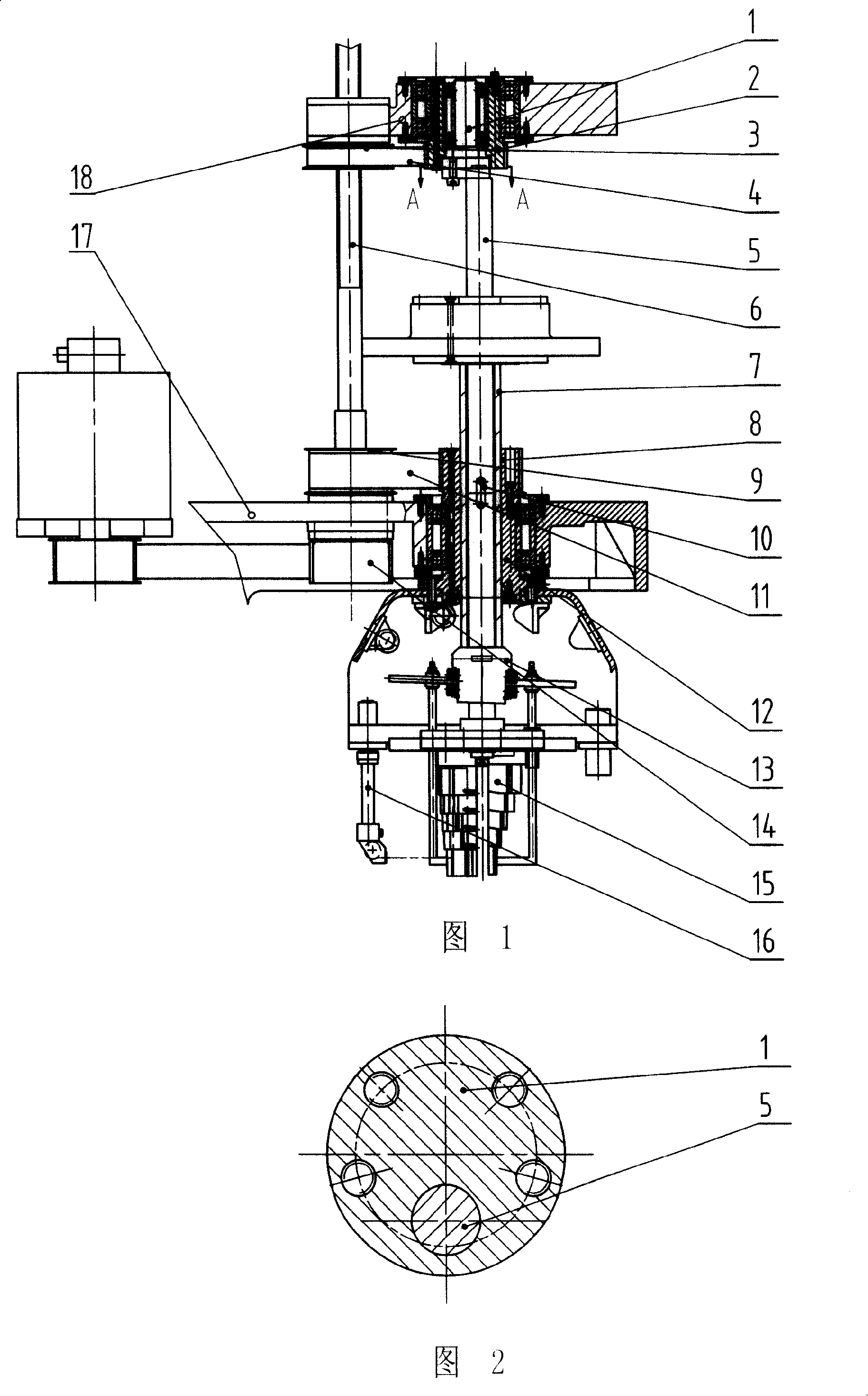
[0010] Refer to Figures 1-2. 1. An eccentric anti-rotation winding device for winding molds, the winding mold 15 is fixedly connected to the lower part of the hanging mold shaft 5 on the frame 17, and the wire pushing sleeve 7 is set on the hanging mold shaft 5 and the eccentric cam cable pushing wire at the lower end The mechanism is fixedly connected, and a spline shaft 6 is set on the frame at the side of the hanger shaft 5, and its outer circle is slidingly matched with the inner hole of the timing pulley 3, and the slider 18 is connected with the timing pulley 3 through a bearing and located on the spline shaft 6 The outer diameter of the connecting shaft 1 is installed on the inner hole of the synchronous pulley 2 through the bearing, and the outer diameter of the synchronous pulley 2 is installed on the slider through the bearing; The end surface is provided with an eccentric boss, and the lower end surface of the connecting shaft 1 is provided with an eccentric groove ...


PUM


Abstract

The invention belongs to mechanical equipments for electrician and particularly relates to a winding former eccentric anti-rotary winding device used in a vertical winding machine. The device is characterized in that a spline shaft is arranged on one side of a framework of a former hanging shaft, the external circle of the spline shaft is sliding fit with an inner bore of a synchronous belt wheel and a sliding block is connected with the synchronous belt wheel via a bearing and located on the spline shaft. An external diameter of a connection shaft is installed via a bearing on the inner bore of the synchronous belt wheel which external diameter is installed on the sliding block via a bearing. The upper end of the former hanging shaft is provided with an eccentric anti-rotary mechanism, which consists of an eccentric boss arranged on the upper end face of the former hanging shaft and an eccentric groove arranged on the lower end face of the connection shaft, which fits with the eccentric boss. The upper end face of the former hanging shaft is fixedly connected with the lower end face of the connection shaft and an enameled wire channel mechanism is arranged on one side of the former hanging shaft. The invention has the advantages of simple structure and manufacturing technology, low manufacturing cost, high driving precision, low noise, high efficiency and long service life.

Description

Technical field: [0001] The invention belongs to electrical mechanical equipment, in particular to an eccentric anti-rotation winding device for a winding die used on a vertical winding machine. Background technique: [0002] The anti-rotation structure of the winding die on the existing vertical winding machine mostly adopts the planetary gear structure, which has complicated processing and manufacturing technology, requires equipment processing accuracy, and high manufacturing cost. The planetary gear is easy to wear and the gear gap increases, which makes the transmission accuracy Defects that reduce production efficiency and service life. Invention content: [0003] The purpose of the present invention is to provide an eccentric anti-rotation winding device for winding dies with simple structure and manufacturing process, low manufacturing cost, high transmission precision, low noise, high efficiency and long service life. [0004] The technical solution of the presen...

Claims


Application Information

Patent Timeline
IPC IPC(8): H01F41/06B65H54/00B65H79/00H01F41/098
Inventor 王伟修姜焕林成学虎
Owner 王伟修
Learn More