Ballast water treatment apparatus and method

一种处理装置、压载水的技术,应用在水处理装置、水/污水处理、自然水体处理等方向,能够解决环境不利影响、难细菌杀灭至满足等问题,达到减轻环境的影响的效果

Inactive Publication Date: 2008-06-04
JFEENGINEERING CORP
View PDF4 Cites 45 Cited by
  • Summary
  • Abstract
  • Description
  • Claims
  • Application Information

AI Technical Summary

Problems solved by technology

Ballast water containing these THMs is then discharged and adversely affects the environment
On the other hand, the method in which hydrogen peroxide is added among the methods described in this laid-open application has a problem that it is difficult to kill bacteria in ballast water by hydrogen peroxide to an extent satisfying the ballast water treatment standard of IMO

Method used


Image

  • Ballast water treatment apparatus and method
  • Ballast water treatment apparatus and method
  • Ballast water treatment apparatus and method

Examples


Embodiment approach 1

[0125] An example of embodiment of the ballast water treatment device according to the present invention will be described in detail with reference to the drawings.

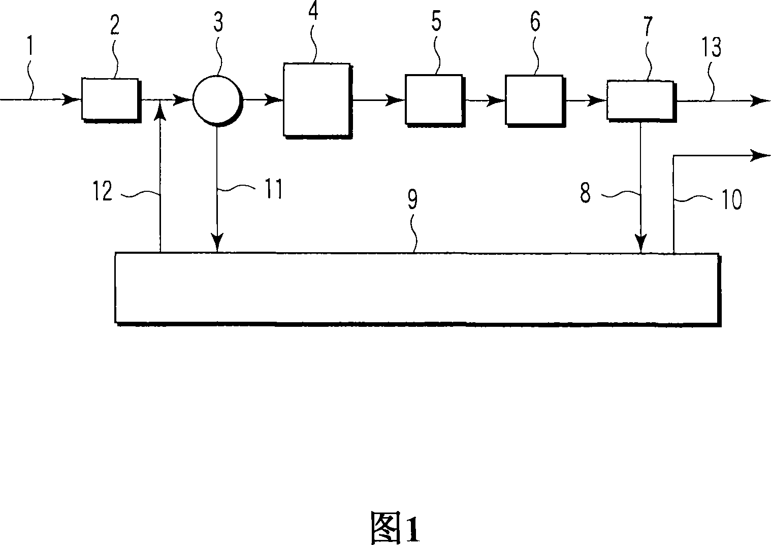
[0126] FIG. 1 is a block diagram of a ballast water treatment apparatus according to a first embodiment of the present invention. This ballast water treatment device has the following structure. The seawater inlet pipeline 1 that introduces seawater into the container. The coarse filter 2 removes coarse matter in the seawater introduced by the seawater inlet pipeline 1 . The pump 3 introduces sea water or ballast water in the ballast tank 9 (described later) to the filter 4 (described later). The filter 4 removes the plankton present in the sea water from which the coarse matter has been removed by the coarse filter 2 . The bactericide supply device 5 supplies a bactericide to the seawater filtered through the filter 4 to kill bacteria and plankton. The fungicide decomposing agent supply device 6 supplies the...

Embodiment approach 2

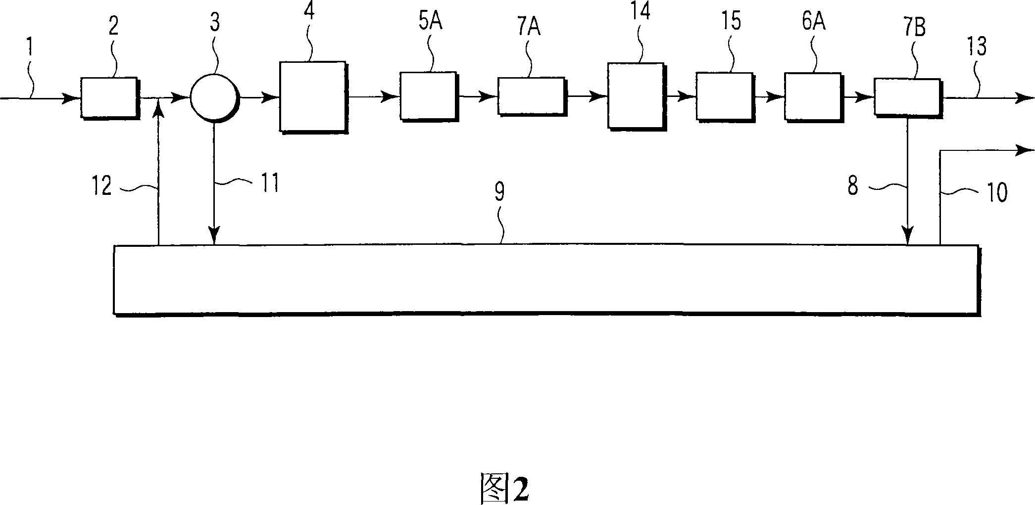
[0199] Fig. 2 is a schematic view according to a second embodiment of the present invention. The same symbols are attached to the same components as those of Embodiment 1. This embodiment differs from Embodiment 1 in that seawater is preserved after supplying the chlorine bactericide to the seawater, treated with hydrogen peroxide, and uses a second venturi. Specifically, a chlorine bactericide is supplied to the filter-filtered seawater before it is introduced into the first venturi. Chlorine bactericide is diffused in seawater by the cavitation generated in the venturi tube, so that the bactericidal effect is improved. Then, the seawater is stored in the storage tank for a predetermined period of time, after which hydrogen peroxide is supplied to the seawater, and then the seawater is introduced into the second venturi tube. Hydrogen peroxide is diffused in seawater by cavitation created in the second venturi.

[0200] In this embodiment, after the chlorine sterilizer is ...

Embodiment approach 3

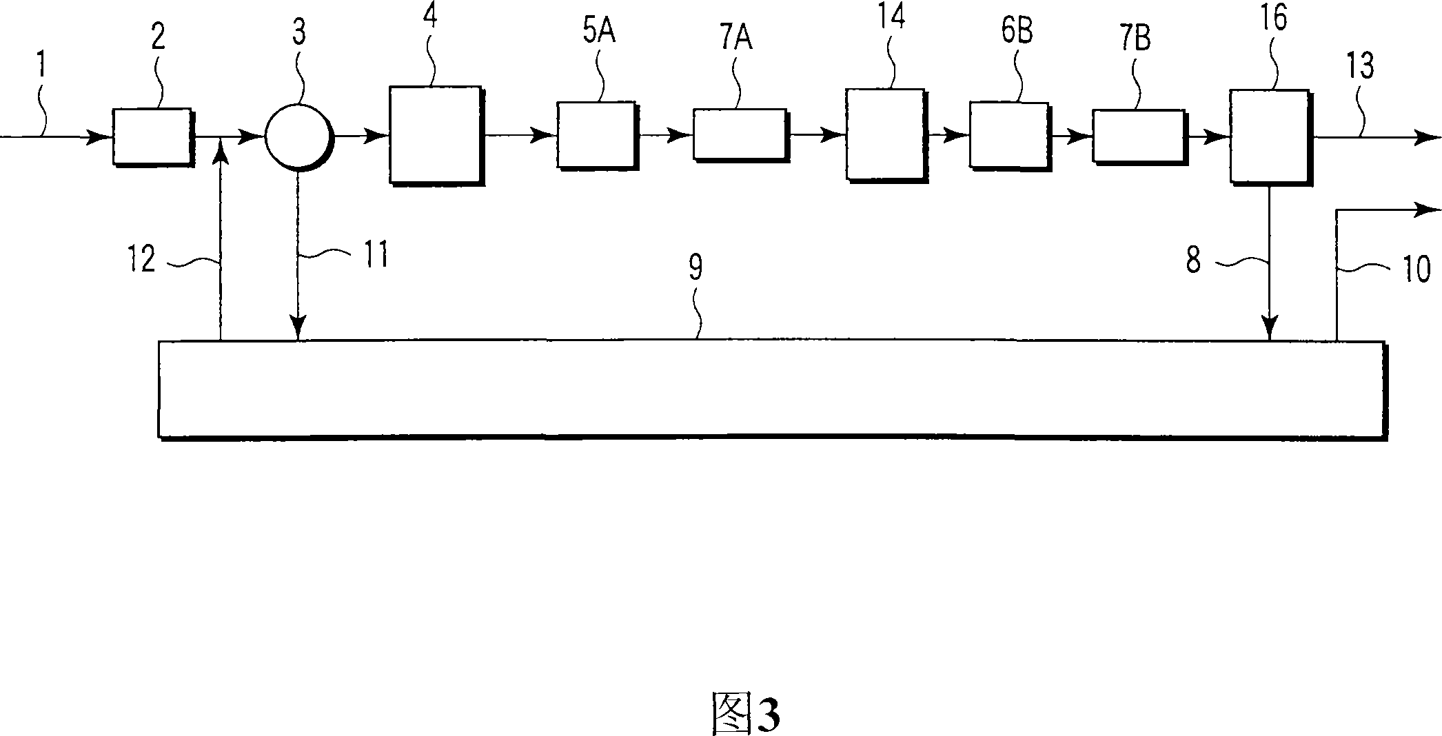
[0232] Fig. 3 is a schematic view according to a third embodiment of the present invention. The same symbols are attached to the same components as those of Embodiment 1. This embodiment differs from Embodiment 1 in that seawater is preserved after supplying chlorine bactericide to seawater, chlorine reducing agent is supplied, a second venturi is used, and activated carbon treatment is performed. Specifically, a chlorine bactericide is supplied to the filter-filtered seawater before it is introduced into the first venturi. The chlorine biocide is diffused in the seawater by the cavitation created in the first venturi. Then, the seawater is stored in the storage tank for a predetermined period of time, after which the chlorine reducing agent is supplied to the seawater, and then the seawater is introduced into the second venturi tube. The chlorine reducing agent is diffused in seawater by cavitation created in the second venturi. The seawater discharged from the second vent...


PUM

PropertyMeasurementUnit
reduction potentialaaaaaaaaaa
sizeaaaaaaaaaa
sizeaaaaaaaaaa

Abstract

A ballast water treatment device which can meet the ballast water standard stipulated by IMO at low cost with certainty. Provided is a ballast water treatment device comprising: a filter unit (4) for filtering seawater to capture aquatic organisms; a bactericide supply unit (5) for supplying a bactericide to the filtered seawater; And Venturi tube (7), this tube is used for introducing the seawater that adds bactericide, and produces cavitation in seawater, thus has not only diffused bactericide but also kills or kills the aquatic organisms of seawater.

Description

technical field [0001] The present invention relates to an apparatus and method for treating ballast water introduced into a ballast tank of a ship, and more particularly to an apparatus and method for effectively killing harmful bacteria and plankton contained in ballast water. Background technique [0002] In general, in ships with little or no cargo, it is necessary to introduce ballast water into the ballast tanks before sailing of these ships, from ensuring the immersion depth of the ship's propulsion plant and ensuring safe navigation when sailing without cargo Inside. Instead, the ballast water is drained when cargo is loaded in port. During this period, if ballast water is introduced and discharged by ships traveling between loading ports and unloading ports with different environments, differences in types of bacteria and microorganisms such as plankton contained in the ballast water cause concerns about damage to coastal ecosystems. Concerns about undesired effec...

Claims


Application Information

Patent Timeline
Patent Type & Authority Applications(China)
IPC IPC(8): C02F1/50B63B13/00C02F1/32C02F1/34C02F1/46C02F1/76
CPCC02F1/76B63B13/00C02F1/32B63J4/002B63J4/004C02F1/001C02F1/283C02F1/34C02F2103/008C02F9/00C02F1/50C02F1/722C02F1/008C02F1/4674C02F2001/46195C02F2209/04C02F2209/11C02F2209/29C02F2303/04C02F2303/185
Inventor 冈本幸彦藤原茂树渊上浩司中原启介猪子正邦石田庄
Owner JFEENGINEERING CORP
Why Eureka
Try Eureka