Hand milling machine capable of preventing blood entering

A technology for milling handpieces and blood, which is applied in the field of milling handpieces for bone tissue cutting, can solve bearing failure. On the one hand, blood may enter the bearing cavity along the gap between the milling cutter and the boot cover; on the other hand, it may, The milling mobile phone is stuck and other problems, to increase the transmission resistance, prevent blood from entering the milling mobile phone, and prolong the maintenance cycle

Active Publication Date: 2008-06-11
CHONGQING XISHAN SCI & TECH
View PDF0 Cites 12 Cited by
  • Summary
  • Abstract
  • Description
  • Claims
  • Application Information

AI Technical Summary

Problems solved by technology

When the existing milling handpiece mills the bone plate, the blood will enter the milling handpiece along the fitting gap between some parts of the milling handpiece; on the one hand, the blood may enter the bearing along the gap between the milling cutter and the boot cover seat cavity; on the other hand, it may enter the bearing seat cavity along the gap between the milling cutter and the drive shaft tube, and through the gap between the steel ball and the sleeve and the drive shaft tube, resulting in corrosion of the bearing by blood and Contaminate the bearing, causing the bearing to fail rapidly or causing the milling handpiece to be stuck and affect the operation
In addition, the coagulated blood inside the mobile phone after surgery is difficult to remove

Method used


Image

  • Hand milling machine capable of preventing blood entering

Examples


Embodiment Construction

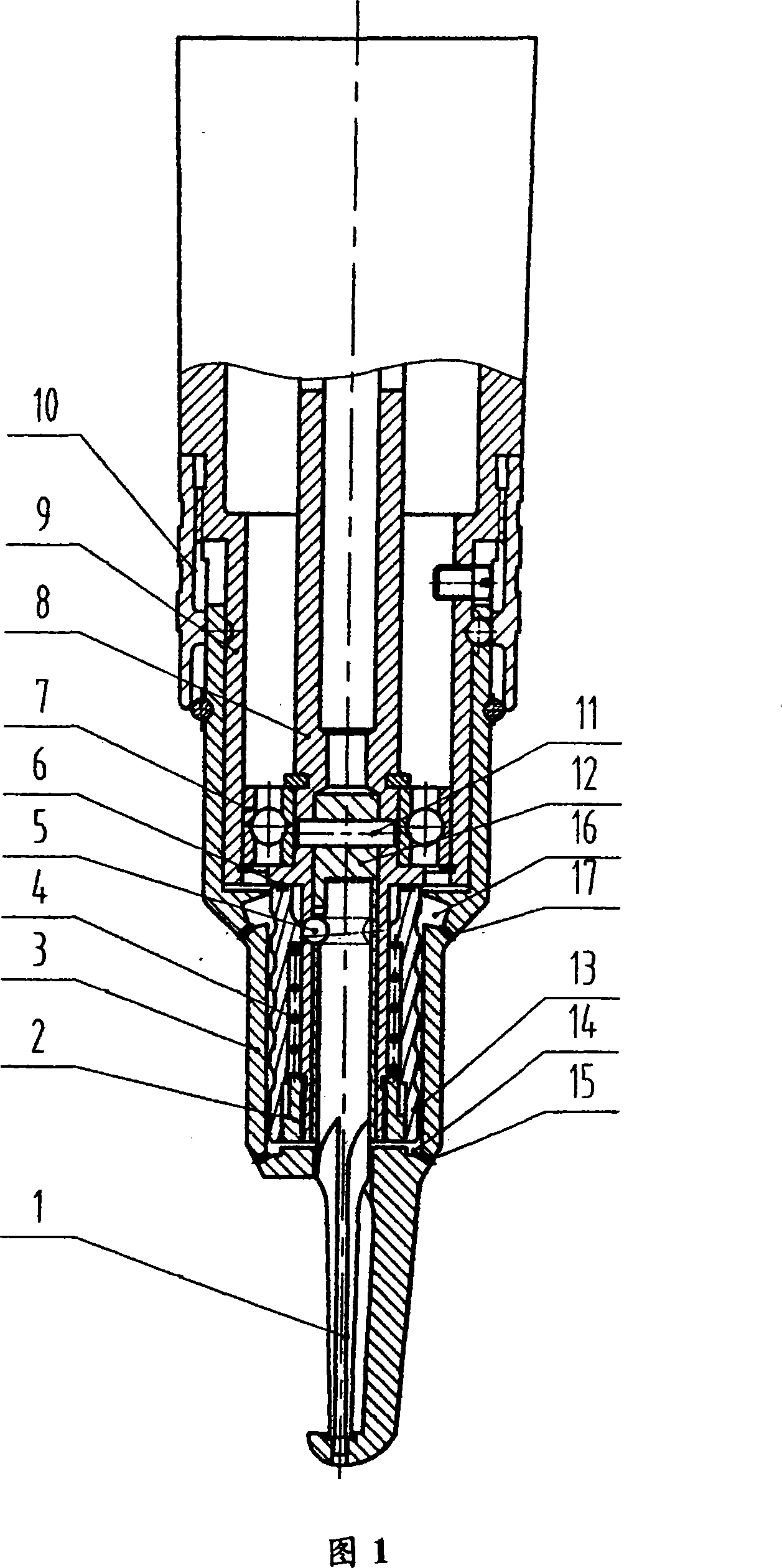
[0009] The present invention will be further described below in conjunction with the accompanying drawings.

[0010] Referring to Fig. 1, the boot cover 3 is fitted on the lower part of the outer sleeve 9, and the locking sleeve 10 is fitted at the junction of the outer sleeve and the boot cover;

[0011] The transmission shaft cylinder 8 is matched in the outer sleeve through the bearing 7, the milling cutter handle sleeve 12 is positioned and connected in the lower part of the transmission shaft cylinder through the connecting pin 11, the sleeve 2 is screwed to the lower end of the transmission shaft cylinder, and the spring 4 is installed On the outside of the lower part of the transmission shaft and on the sleeve, the upper part of the milling cutter 1 passes through the hole in the lower part of the boot cover and is positioned and connected in the milling cutter handle through the steel ball 5. The lower end of the milling cutter and the lower end of the boot cover The h...


PUM


Abstract

The invention relates to a milling handset for preventing the entering of blood, which comprises an outer sleeve, a boot sleeve which is engaged with the lower part of the outer sleeve, a driving shaft cylinder which is engaged in the outer sleeve, a milling cutter sleeve which is fixedly connected in the lower part of the driving shaft cylinder, a sleeve which is connected with the lower end of the driving shaft cylinder through threads, a hole whose upper part penetrates into the lower part of the boot sleeve and a milling cutter which is fixedly connected in the milling cutter sleeve through steel balls. The invention is characterized in that a spiral sealing sleeve is arranged on the outer sides of the lower portions of the sleeve, the spring and the driving shaft cylinder, the outer side of the spiral sealing sleeve is engaged with the inner wall of the lower part of the boot sleeve, a liquid outlet ring groove is arranged on the bottom of the boot sleeve, liquid outlets are arranged along the bottom of the liquid outlet ring groove, a relief overflow ring groove is arranged on the middle part of the boot sleeve, and overflow holes are arranged along the bottom of the relief overflow ring groove. The invention can effectively prevent blood from entering into the inner portion of the milling handset, largely prolongs the maintenance cycle of the milling handset, and excellently meets the clinical requests.

Description

technical field [0001] The invention relates to a medical device, in particular to a milling handpiece capable of preventing blood from entering, especially a milling handpiece used for bone tissue cutting. Background technique [0002] The milling handpiece (that is, a surgical manipulator) is a tool for bone tissue cutting in surgical operations. After the milling cutter is installed, the high-speed movement of the milling cutter under the power drive can quickly and accurately cut the bone tissue. When the existing milling handpiece mills the bone plate, the blood will enter the milling handpiece along the fitting gap between some parts of the milling handpiece; on the one hand, the blood may enter the bearing along the gap between the milling cutter and the boot cover seat cavity; on the other hand, it may enter the bearing seat cavity along the gap between the milling cutter and the drive shaft tube, and through the gap between the steel ball and the sleeve and the driv...

Claims


Application Information

Patent Timeline
Patent Type & Authority Applications(China)
IPC IPC(8): A61B17/56A61B17/32
Inventor 郭毅军周坤
Owner CHONGQING XISHAN SCI & TECH
Why Eureka
Try Eureka