
Ultra-high frequency electronic label for metallic material surface

A technology of electronic tags and metal materials, which is applied to record carriers used in machines, instruments, computer parts, etc., can solve the problems of high cost of ferrite materials and unfavorable promotion of RFID products, and achieve remarkable results

Inactive Publication Date: 2008-06-11
SHANGHAI FUDAN MICROELECTRONICS GROUP
View PDF0 Cites 11 Cited by
  • Summary
  • Abstract
  • Description
  • Claims
  • Application Information

AI Technical Summary

Problems solved by technology

However, due to the diversity of RFID application environments and the differences in metal surface characteristics, the characteristics of ferrite materials provided by different material suppliers are also very different, which brings a lot of inconvenience to subsequent processing and production, generally through actual matching. Test to determine which type of ferrite material to choose, and repeat the test back and forth many times
And the cost of ferrite material itself is also higher
Restricted by the external use environment, the final RFID product may not fully meet the actual use requirements of customers, which is not conducive to the vigorous promotion of RFID products

Method used


Image

  • Ultra-high frequency electronic label for metallic material surface

Examples


Embodiment Construction

[0020] The structural features of the RFID of the present invention will be further described below in conjunction with the accompanying drawings.

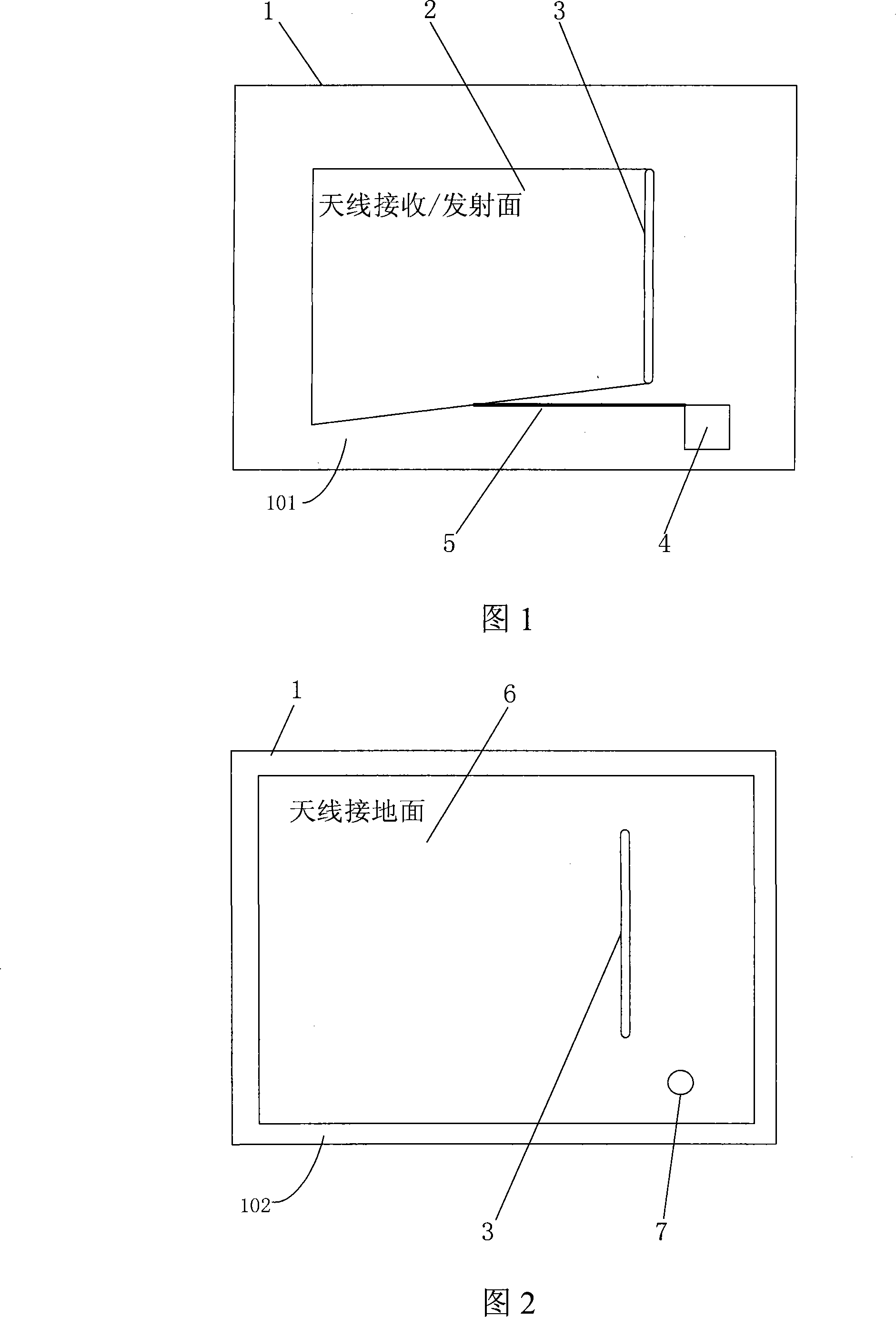
[0021] As shown in Figures 1 and 2, the RFID of the present invention includes: a substrate 1, a chip 4 of an electronic label placed on the substrate 1, a feeder 5 connected to the chip 4, and a microstrip antenna, which is received / emitted by the antenna Surface 2 (shown in Figure 1), antenna ground plane 6 (shown in Figure 2) and feeder 5 (shown in Figure 1). The receiving / transmitting surface 2 of the antenna is placed on the side on which the chip 4 and the feeder 5 are placed on the substrate 1, and this substrate surface is the front side 101 of the electronic label (shown in Figure 1); the antenna grounding surface 6 is placed on the side of the substrate 1 On the other hand, this substrate surface is the back side 102 (shown in Figure 2) of the electronic label; the antenna receiving / transmitting surface 2 is connected wi...


PUM

PropertyMeasurementUnit
Thicknessaaaaaaaaaa

Abstract

An ultrahigh frequency electronic label used for metal material surface comprises a substrate, a chip of the electronic label placed on the same surface of the substrate, a feeder line and an antenna receiving / emitting surface, wherein, the substrate surface is the front of the electronic label; an antenna grounding surface is placed on the other surface of the substrate, and the substrate surface is the back of the electronic label; the antenna receiving / emitting surface on the front is connected with the antenna grounding surface on the back through a short circuit groove to form a microstrip antenna; the chip is connected with the antenna receiving / emitting surface through the feeder line; grounding end of the chip is connected with the antenna grounding surface on the back via a through hole; the antenna grounding surface on the back is in direct contact with the surface of a metal material using the electronic label. As the self back of the electronic label is the grounding surface, the shielding effect of the metal material surface does not need to be considered completely. Due to the short circuit groove, the area of the microstrip antenna can be reduced by about a half. Therefore, the size of the electronic label can be reduced.

Description

technical field [0001] The invention relates to an ultra-high frequency electronic tag, in particular to an ultra-high frequency electronic tag (RFID) used on the surface of metal materials. Background technique [0002] RFID (electronic tag) technology is a technology that uses radio frequency signals to achieve non-contact information transmission through spatial coupling and achieves identification purposes through the transmitted information. It is the specific application and development of automatic identification technology in radio microwave technology. As a technology that can quickly and accurately collect and process information, it is recognized by the world as one of the top ten important technologies in the 21st century. Experts say that it will affect the global economy and people's lives after mobile communication technology and Internet technology. A revolutionary new technology. Its unique waterproof, antimagnetic, high temperature resistance, long service...

Claims


Application Information

Patent Timeline
IPC IPC(8): G06K19/077
Inventor 金玮沈磊宁兆熙白亮
Owner SHANGHAI FUDAN MICROELECTRONICS GROUP
Learn More