D type optical fiber clamp

An optical fiber and grinding technology, which is applied in the direction of grinding/polishing equipment, grinding machines, manufacturing tools, etc., can solve the problem of D-shaped optical fiber being fragile, and achieve the effects of low cost, reduced operation requirements, and reduced cost

Inactive Publication Date: 2008-06-18
CHANGCHUN INST OF OPTICS FINE MECHANICS & PHYSICS CHINESE ACAD OF SCI
View PDF0 Cites 4 Cited by
  • Summary
  • Abstract
  • Description
  • Claims
  • Application Information

AI Technical Summary

Problems solved by technology

[0005] In order to solve the problem of making D-shaped optical fiber fragile in the background technology, the present invention provides a D-shaped optical fiber grinding jig

Method used


Image

  • D type optical fiber clamp
  • D type optical fiber clamp
  • D type optical fiber clamp

Examples


Embodiment Construction

[0023] Concrete implementation steps of the present invention are as follows:

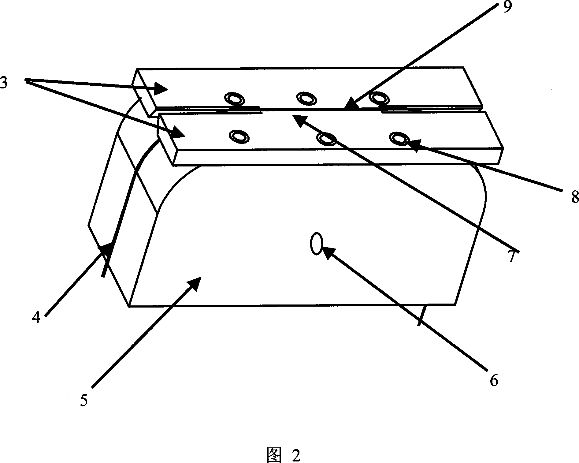
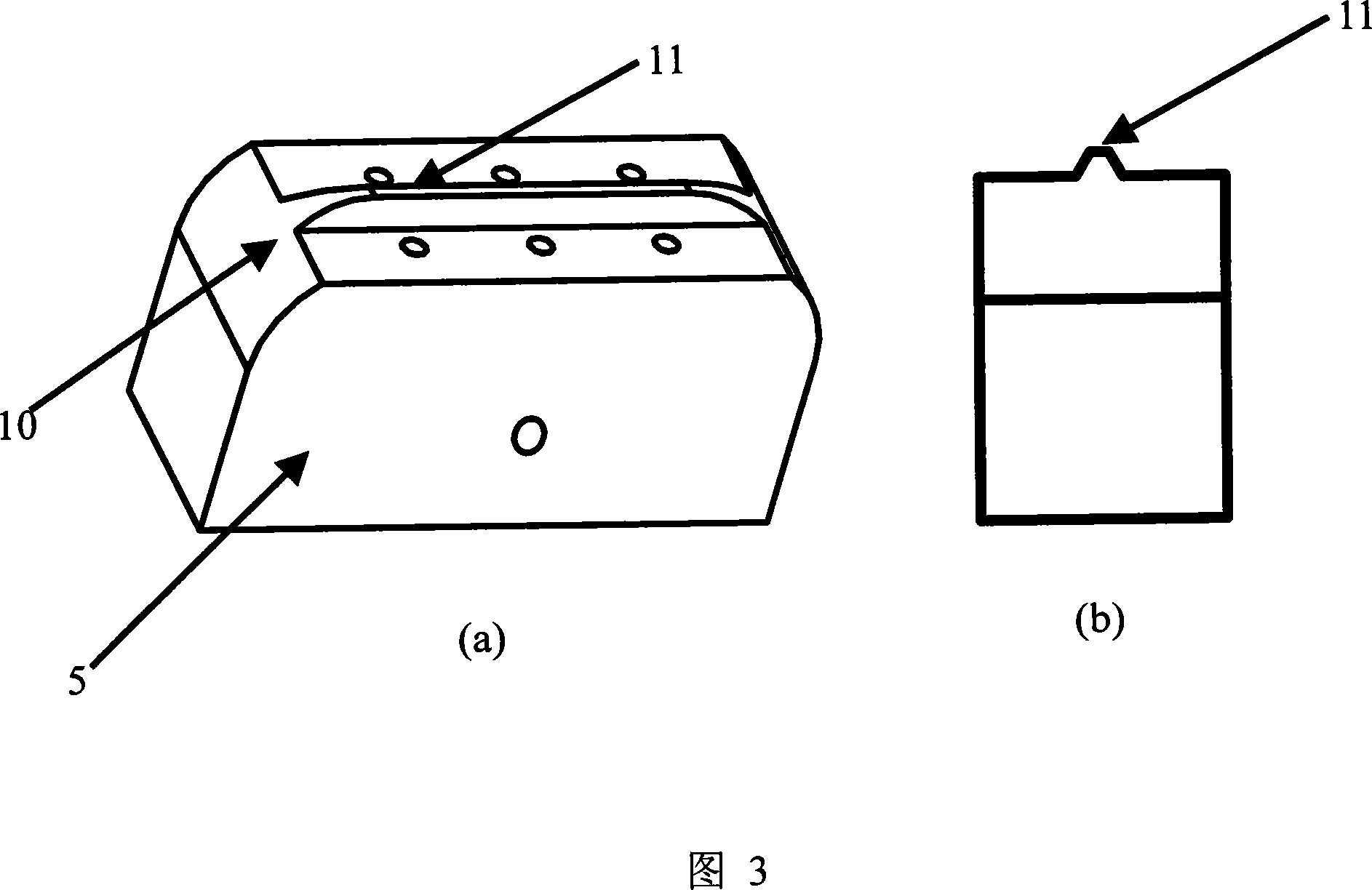
[0024] 1. Adopt 00Cr12 stainless steel plate, process the base 5 of the fixture according to Figure 2, the base length is 60 mm, the height is 30 mm, and the width is 20 mm. 1.5 millimeters at the bottom of trapezoidal table top 11, trapezoidal base angle 60 degrees, high 2.6 millimeters. The screw holes 6 on both sides of the base are M6-7H type, the depth of tapping is 5 mm, and the depth of the hole is 6 mm. The distance between any one of them and the base bottom surface is 7 mm, and the other is 18 mm. The specification of the screw hole for fixing the pressure plate is M2-7H type, the tapping depth is 5mm, and the hole depth is 6mm.

[0025] 2. Use 00Cr12 stainless steel plate to process the front and rear pressure plates 3 of the fixture. The length of the pressure plate is 54 mm, the height is 3 mm, and the width is 10 mm. Three holes with a diameter of 2.6 mm are drilled on each pressure ...


PUM


Abstract

The invention belongs to the special optical fiber producing technical field, which is a clamp for grinding a D shaped optical fiber. A base and a front and a back pressure plate of the clamp are produced in mechanical technology and are assembled to form an optical fiber groove for fixing the optical fibers. And then the depth of the optical fiber groove is controlled through the grinding allowance for grinding the front and the back pressure plates being controlled. A screw hole is drilled respectively at the different height on medial axis at the two sides of the base of the clamp; the clamp and a grinder clamp are fixed by a bolt through the hole, so that the clamp has the characteristic of self leveling. The invention uses the microscopic mechanical processing to realize the micron processing technique, the grinding and the packaging of the optical fiber are combined well. The invention has the advantages of reliable operating performance, strong impact resistance ability, easy processing and low cost; after the invention is assembled, the manufacture cost and difficulty are decreased, the flexibility is increased and the maintenance becomes convenient through the processing technique, and the clamp is convenient to be used with the self leveling characteristic.

Description

technical field [0001] The invention belongs to the technical field of making special optical fibers, and relates to a grinding jig for making D-shaped optical fibers, which is the core part of D-shaped optical fiber sensors in the fields of medical detection, environmental monitoring, biological warfare agent detection and the like. Background technique [0002] The optical fiber evanescent field sensor is based on the principle of attenuated total internal reflection (ATR). The energy transmitted in the optical fiber will expand into the optical fiber cladding due to the existence of the evanescent field, resulting in a corresponding decrease in the output light intensity of the optical fiber. When the cladding of the fiber is removed and the measured substance directly contacts the fiber core, the measured substance will directly absorb the energy of the evanescent field of the fiber. At this time, the attenuation of the transmitted light intensity in the fiber directly re...

Claims


Application Information

Patent Timeline
Patent Type & Authority Applications(China)
IPC IPC(8): B24B19/08
Inventor 吴一辉庄须叶王淑荣
Owner CHANGCHUN INST OF OPTICS FINE MECHANICS & PHYSICS CHINESE ACAD OF SCI
Why Eureka
Try Eureka