
Improved magnetic head tabs combination, magnetic disk drive and manufacturing method thereof

A disk drive and magnetic head technology, which is applied in the direction of aligning the magnetic track on the disk, driving/moving the recording head, supporting the head, etc., and can solve problems such as damage to the piezoelectric element, cracking or scratching of the surface area of ​​the piezoelectric sheet, and damage to the piezoelectric sheet.

Inactive Publication Date: 2011-05-11
SAE MAGNETICS (HK) LTD
View PDF3 Cites 0 Cited by
  • Summary
  • Abstract
  • Description
  • Claims
  • Application Information

AI Technical Summary

Problems solved by technology

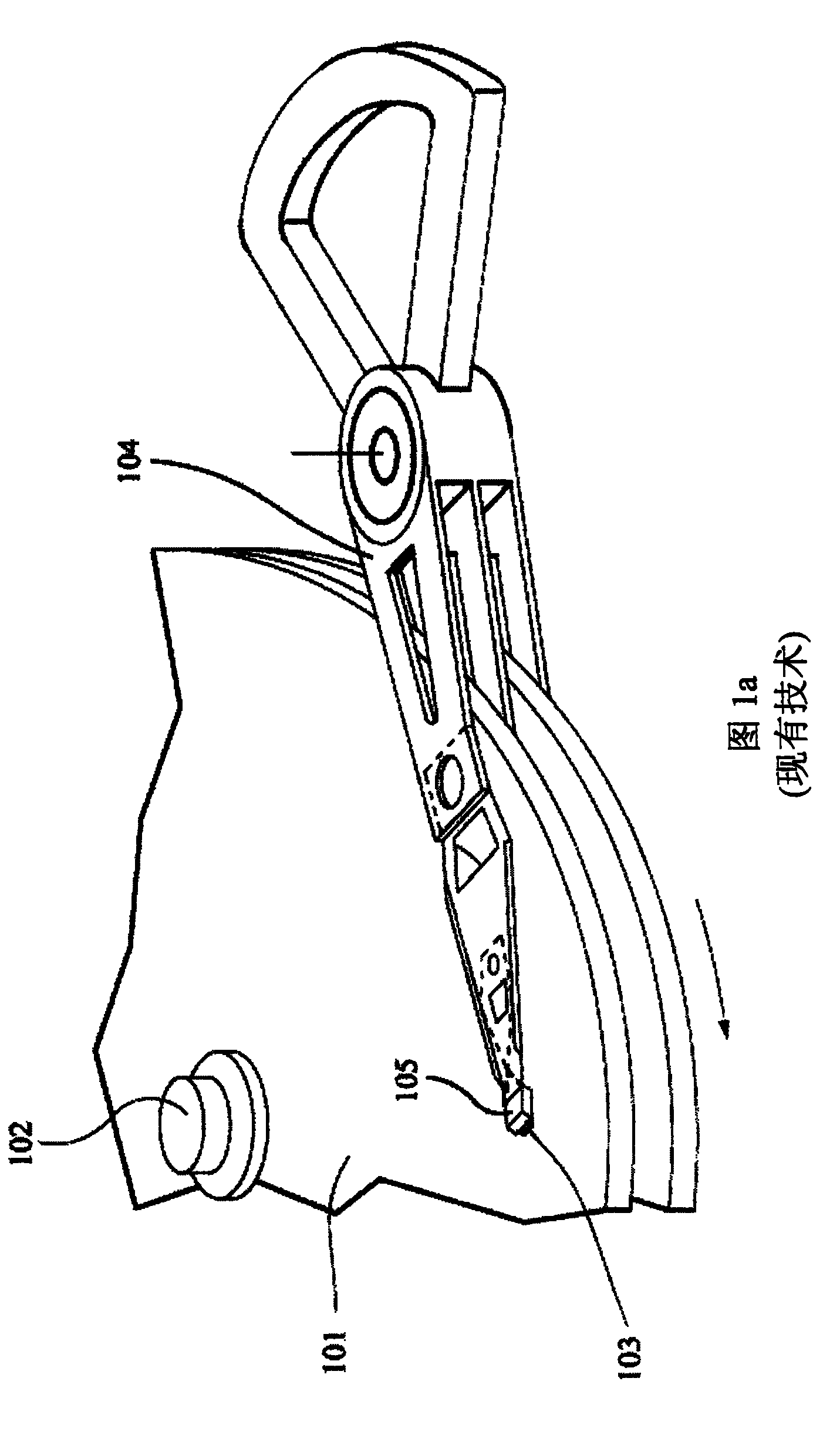
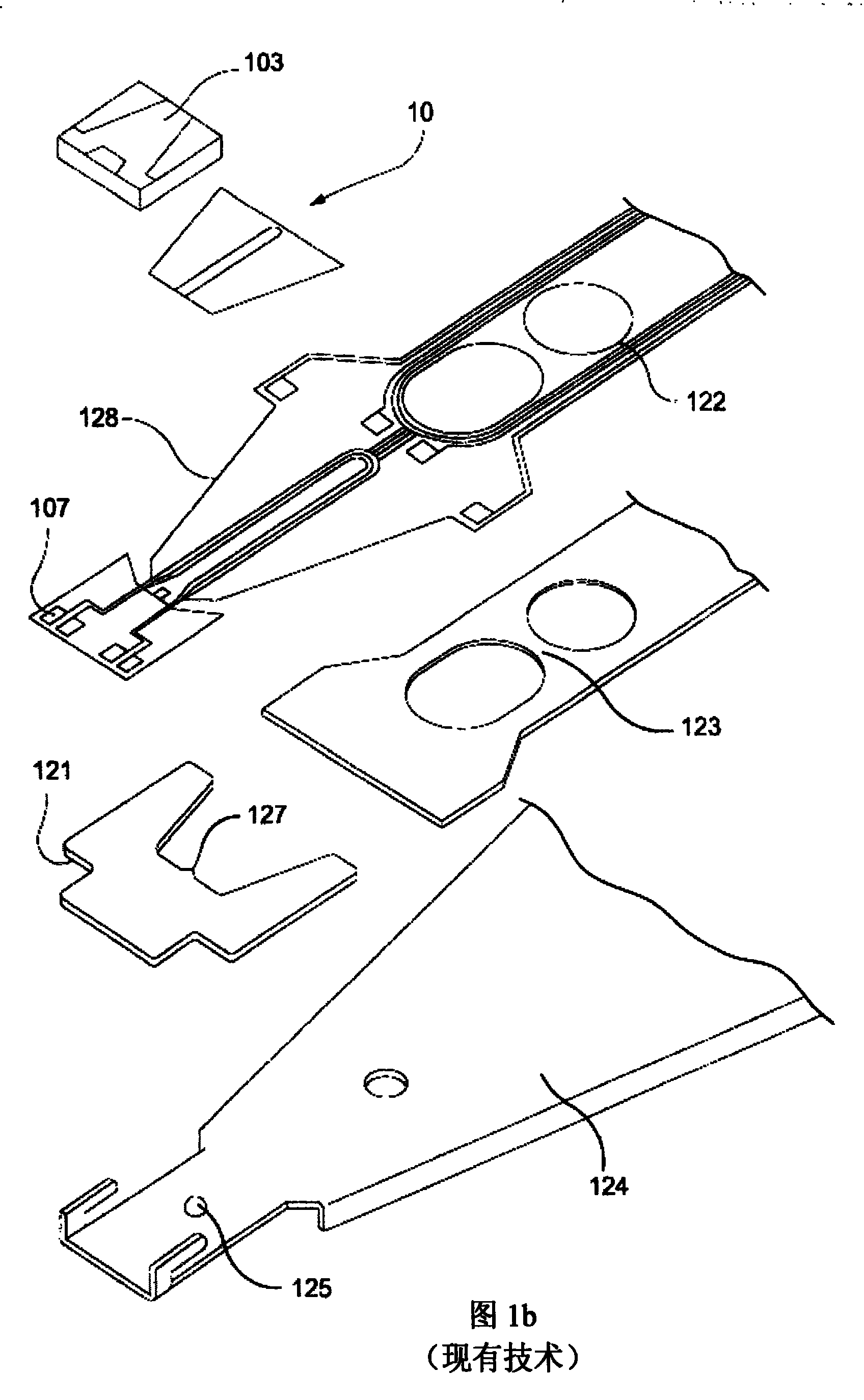
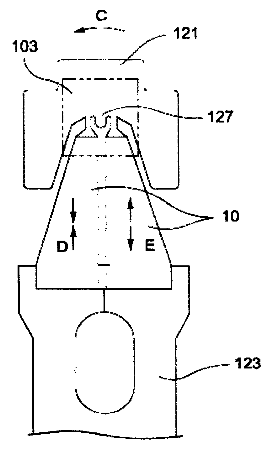
Because the front part of the magnetic head has sharp edges and corners, it may cause cracks or scratches on the surface area 130 of the piezoelectric sheet, thereby causing damage to the piezoelectric element, especially when the piezoelectric sheet is made of a thin film material, it is more likely to cause Damage to the piezo

Method used


Image

  • Improved magnetic head tabs combination, magnetic disk drive and manufacturing method thereof
  • Improved magnetic head tabs combination, magnetic disk drive and manufacturing method thereof
  • Improved magnetic head tabs combination, magnetic disk drive and manufacturing method thereof

Examples


Embodiment Construction

[0040] Conventional HGAs have a large cantilevered tongue area and thus require a parallel gap. However, such a structure easily damages the piezoelectric element, as described above. Therefore, the present invention aims to reduce the size of the tongue area, reduce or even eliminate the need for gaps, and ensure the performance of the HGA even when vibrations occur.

[0041] Embodiments of the present invention will now be described with reference to the drawings. FIG. 2 a is a perspective view of a HGA with a thin-film piezoelectric microactuator according to an embodiment of the present invention. The HGA 200 shown in FIG. 2 a includes a load bar 204 , a flexible member 209 , a pivot member 213 and a substrate 212 . The magnetic head 210 is partially installed on the top area of ​​the tongue of the flexible member 209 and the bottom area of ​​the tongue of the flexible member 209 . Two piezoelectric elements 202 are installed in the middle area of ​​the flexible member ...


PUM


Abstract

The invention discloses an accurate position adjustment system of a thin film piezoelectric micro-actuator and a method thereof. A magnetic head folding chip composition is provided in a plurality of embodiment, which comprises a cantilever part. The cantilever part comprises a cantilever flexible part that is arranged at one end of the cantilever part and the cantilever flexible part comprises aligule area. At least a micro-actuator is assembled at a micro-actuator installation area of the ligule area of the cantilever flexible part. Space between the magnetic head and the micro-actuator isreduced or eliminated. The magnetic head is fully and wholly assembled on an insulation layer that separates the magnetic head from the micro-actuator. The cantilever flexible part is fully and wholly arranged under the magnetic head and the ligule area of the cantilever flexible part is fully and equably forced by salient points formed on the cantilever part. A supporting node or a plurality of supporting nodes is / are formed on the cantilever flexible part and used for improving the hardness of the cantilever flexible part.

Description

technical field [0001] The invention relates to an information recording disk drive, in particular to an improved magnetic head flap assembly and its manufacturing method, so that the position adjustment of the thin-film piezoelectric micro-actuator is more accurate. Background technique [0002] A common type of information storage device is a magnetic disk drive system that uses magnetic media to store data and a moveable read / write head positioned over the magnetic media to selectively read data from and write data to the magnetic media superior. [0003] Consumers always want the storage capacity of the disk drive to be as large as possible, but also to read and write operations more quickly and accurately. Therefore disk drive manufacturers have been continuously developing higher capacity disk drives. For example, increasing the density of the magnetic tracks by reducing the track width or the track pitch on the magnetic disk can indirectly increase the storage capac...

Claims


Application Information

Patent Timeline
Patent Type & Authority Patents(China)
IPC IPC(8): G11B5/596G11B21/10G11B21/21
Inventor 姚明高
Owner SAE MAGNETICS (HK) LTD
Learn More