
Sliding part and its manufacturing method

A sliding part, manufacturing method technology, applied in the direction of anti-centrifugal force rotating parts, bearing elements, transportation and packaging, etc., to achieve the effect of low friction coefficient, superior durability and good durability

Active Publication Date: 2011-12-28
DIAMET CORP
View PDF1 Cites 0 Cited by
  • Summary
  • Abstract
  • Description
  • Claims
  • Application Information

AI Technical Summary

Problems solved by technology

[0005] However, in the former and the latter prior art, by mixing the iron-based raw material powder and the iron-based raw material powder with a larger aspect ratio than the The mixed powder of copper-based flat raw material powder composed of flat powder is filled in the filling part of the molding die, and at the same time, vibration is applied to make the copper-based flat raw material powder segregate outside the filling part, so that the copper-based flat raw material powder is in the direction of thickness. overlapped on each other, and the direction crossing the thickness coincides with the longitudinal direction of the surface side, concentrated and segregated on the surface side, however, on the surface, not only the segregated copper-based flat raw material powder is exposed, but also exposed in a part of it. Iron-based raw material powder is formed, so gaps are formed between adjacent copper-based flat raw material powders exposed on the surface, as a result, gaps between copper-based raw material powders and iron-based raw material powders are formed on the surface, and copper-based raw material powders are formed on the surface. A gap between the flat raw material powders that prevents the surface copper coverage of the sliding part from being improved

Method used


Image

  • Sliding part and its manufacturing method
  • Sliding part and its manufacturing method
  • Sliding part and its manufacturing method

Examples


Embodiment 1

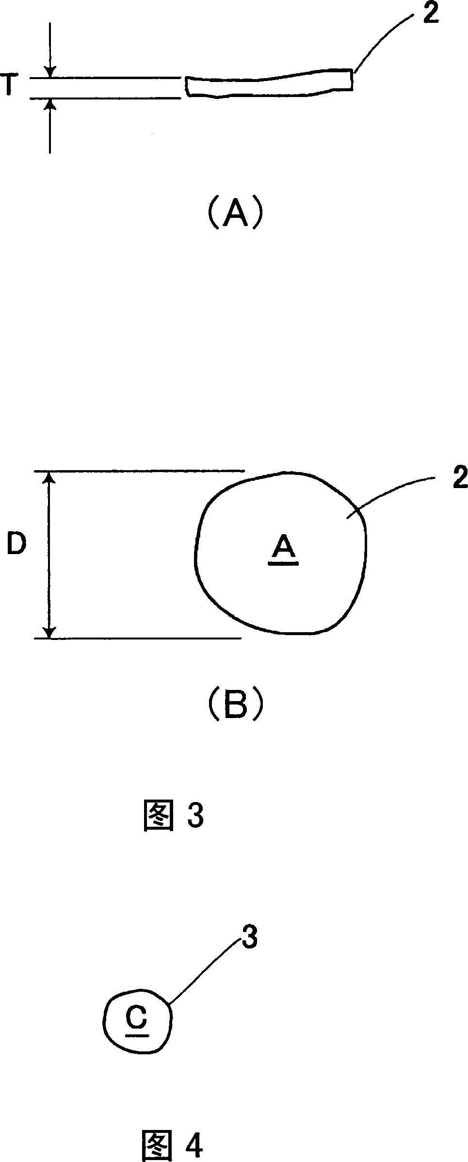
[0036] Next, the production method of the present invention will be described. Iron-based raw material powder 1, copper-based flat raw material powder 2, and copper-based small raw material powder 3 are mixed in a predetermined ratio (S1). Such as figure 2 As shown, as the iron-based raw material powder 1 , a substantially spherical irregular-shaped powder such as atomized powder is used. The average diameter of the iron-based raw material powder 1 is 50 to 100 μm, preferably 60 to 80 μm. Additionally, if image 3 As shown, as the copper-based raw material powder 2, flat powder is used, and the aspect ratio (aspect ratio) (diameter D / thickness T) of the flat powder is 10 or more, preferably 20-50. The flat copper-based flat raw material powder 2 has an average diameter D of 80 μm and an average thickness T of 1 to 5 μm. In addition, as the copper-based flat raw material powder 2 , a powder mainly composed of copper powder and mixed with 2 to 30% by weight of tin powder ca...


PUM

PropertyMeasurementUnit
diameteraaaaaaaaaa

Abstract

There is provided a sliding part in which a surface coverage ratio of copper in the sliding part increases. A bearing which is the sliding part is formed by filling the raw powder into the filling portion of the forming mold, compacting the raw powder to form a powder compact 6, and sintering the powder compact 6. A copper-based raw powder is composed of a copper-based flat raw powder 2 having an average diameter smaller than that of an iron-based raw powder 1 and an aspect ratio larger than that of the iron-based raw powder 1, and a copper-based small-sized raw powder 3 having the average diameter is smaller than that of the copper-based flat raw powder 2. The copper is allowed to segregate at the surface of the sliding part. In the bearing in which the copper-based flat powder 2 segregates at the surface, the surface is covered with the copper-based small-sized raw powder 3 that has emerged on the surface, as well as the copper-based flat raw powder 2, thereby it is possible to increase the surface coverage ratio of copper.

Description

technical field [0001] The present invention relates to a sliding member such as a bearing and a manufacturing method thereof. Background technique [0002] As a sliding part that can reduce frictional resistance, improve durability, and prevent noise, it is known that iron-based and copper-based raw material powders are filled in the filling part of a molding die, while vibration is applied, and the raw material powders are subjected to vibration. Pressing to form a compact and then sintering the compact, wherein the copper-based raw material powder is a flat powder with a larger aspect ratio than the iron-based raw material powder, and is segregated on the surface side Copper (for example, Patent Document 1); by filling iron-based and copper-based raw material powders in the filling portion of a molding die, while applying vibration, and pressurizing the raw material powders to form compacts, and then the compacts A sliding part formed by sintering, wherein the copper-ba...

Claims


Application Information

Patent Timeline
Patent Type & Authority Patents(China)
IPC IPC(8): B22F5/00F16C33/12B22F1/00F16C33/14B22F3/02
CPCB22F2998/10F16C33/12B22F5/106B22F2998/00F16C33/14F16C2204/60F16C2220/20B22F1/00B22F3/02B22F3/10B22F1/068B22F5/00B22F3/12
Inventor 清水辉夫丸山恒夫
Owner DIAMET CORP
Learn More