
Permanent-magnet gyratory agitation device

A technology of rotating stirring and permanent magnets, applied in the directions of dissolution, mixer, chemical instruments and methods, etc., can solve the problems of uneven distribution of the magnetic field of the reaction tank, reduced magnetic force, and reduced rotational power, and achieves low shear force and speed regulation. Low power and the effect of promoting dispersion

Inactive Publication Date: 2008-06-25
INST OF PROCESS ENG CHINESE ACAD OF SCI
View PDF1 Cites 2 Cited by
  • Summary
  • Abstract
  • Description
  • Claims
  • Application Information

AI Technical Summary

Problems solved by technology

[0005] In the Chinese patent application (application number: 200610089480.9) titled "Extraction Device with Rotating and Stable Magnetic Stirring and Its Operation Method", a magnetically agitated dispersing method using a magnetically functional hydrophobic ionic liquid as an extractant is disclosed. The extraction device of the system includes a reaction tank whose bottom middle part is concave inward, and there is a vertical circular NdFeB permanent magnet connected with the shaft of the rotating motor in the groove; on the lower side of the reaction tank A magnetic ionic liquid outlet is opened on the wall of the reactor, a magnetic ionic liquid inlet and a feed liquid inlet are opened on the wall on the other side, and a magnetically stable bed coil is installed on the outer wall of the upper part of the reactor; in the reactor, a circular distribution The liquid inlet of the device is connected to the feed liquid inlet; the magnetically stable bed coil controls the mutual collision and condensation of the magnetic ionic liquid droplets in the dispersed phase; however, the magnetic field in the reaction tank of the device increases with the distance from the permanent magnet. The increase of , attenuation by the square, caused the uneven distribution of the magnetic field in the reaction tank, and the decrease of magnetic force, which resulted in the decrease of rotational power

Method used


Image

  • Permanent-magnet gyratory agitation device
  • Permanent-magnet gyratory agitation device
  • Permanent-magnet gyratory agitation device

Examples


Embodiment Construction

[0036] The present invention will be further explained and illustrated below in conjunction with specific embodiments.

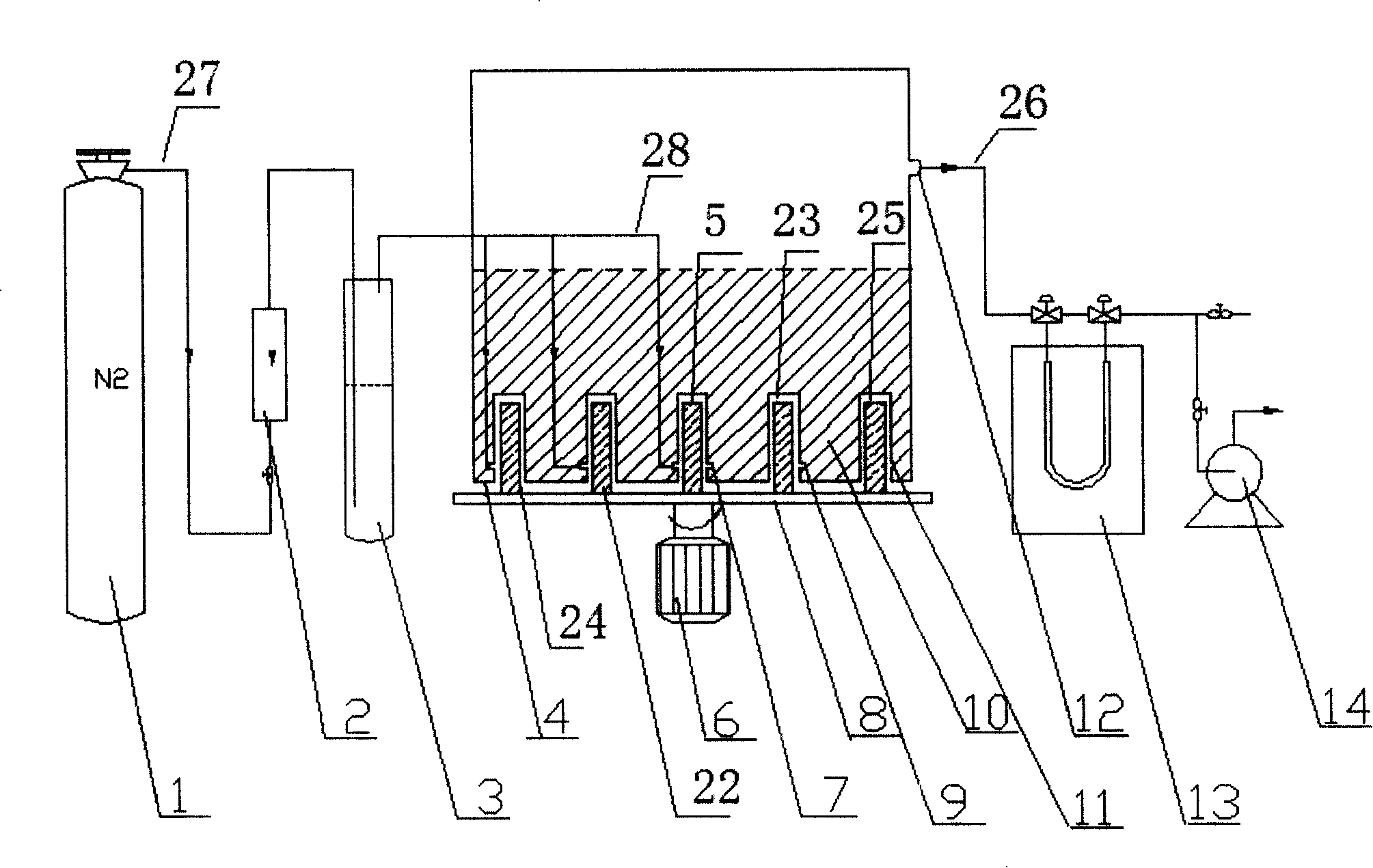
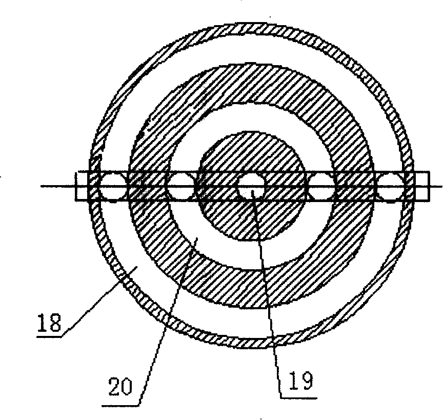
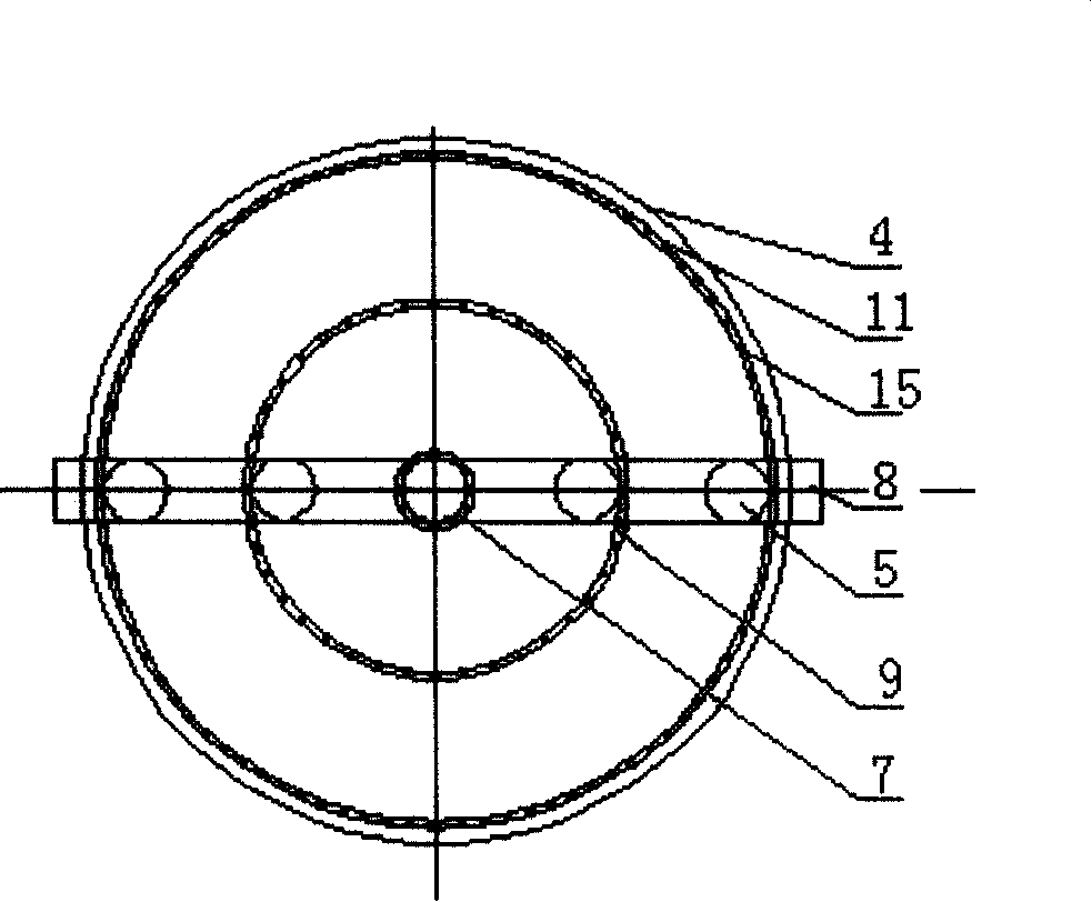
[0037] Such as figure 1 The shown system for measuring the absorption of benzene vapor by magnetic ionic liquid adopts the permanent magnet rotating stirring device of the present invention, and the nitrogen cylinder 1 is connected to the bottom of the solute storage tank 3 through the first gas path 27, and the first gas path is provided with The gas flow meter 2, the upper part of the solute storage tank 3 are respectively connected to the first, second and third annular gas distributors 7, 9, 11 through the second gas path 28, and the first, second and third annular gas distributors Devices 7, 9, 11 are fixed on the bottom of the cylindrical container 4 and placed concentrically, such as Figure 2b with Figure 2a As shown, except that there is a central magnet groove 19 for accommodating the first permanent magnet 5 at the bottom of the container 4, tw...


PUM


Abstract

The invention provides a permanent magnet rotating and stirring device, which comprises a hermetic container (4) that contains magnetic ion liquid (10), a first permanent magnet (5) and a rotating motor (6); the container (4) is provided with an inwards-protuberant central magnet groove (19) at the center of the bottom; the first permanent magnet is positioned in the inwards-protuberant central magnet groove (19); the rotating motor (6) drives the first permanent magnet to rotate in the inwards-protuberant central magnet groove (19). The device is characterized in that the container (4) is also provided with at least one ring-shaped magnet groove and at least one second permanent magnet (22) that is positioned in the ring-shaped magnet groove and can rotate along the ring-shaped magnet when driven by the rotating motor (6); and direction of magnetic pole of the second permanent magnet (22) is the same with direction of magnetic pole of the first permanent magnet (5). The invention overcomes the defect of the existing permanent magnet rotating and stirring devices that as distance from the magnetic ion liquid to the permanent magnet is increased, magnetic force is reduced, which weakens rotating drive.

Description

technical field [0001] The invention relates to a stirring device, in particular to a permanent magnet rotating stirring device with a magnetic ionic liquid as a medium. technical background [0002] The magnetically stabilized bed is a gas-liquid reactor researched for the application of magnetic catalysts. That is, several sets of fixed coils are added outside the reactor. When the current passes through the coils, a magnetic field is generated, and the magnetic catalyst particles are arranged regularly under the action of the magnetic field. The bubbles in the reactor have the effect of breaking and cutting, and the magnetic particle catalyst will not be taken out of the reactor with the high-speed flow of the reaction medium and lost. At the same time, the magnetic catalyst can be recovered by using the magnetic field. The magnetically stabilized bed has achieved satisfactory results in the industry, and its superiority has been shown in the hydrofining process of caprol...

Claims


Application Information

Patent Timeline
IPC IPC(8): B01F13/08
Inventor 刘会洲江洋洋郭晨安震涛
Owner INST OF PROCESS ENG CHINESE ACAD OF SCI
Learn More