
Coated-product with marking, process for manufacturing the same, and enclosure for electronic apparatus

一种涂层、产品的技术,应用在电子设备用外壳领域,能够解决产品不能正确地显现颜色、不良印刷质量、改变等问题

Inactive Publication Date: 2008-06-25
SONY CORP
View PDF8 Cites 32 Cited by
  • Summary
  • Abstract
  • Description
  • Claims
  • Application Information

AI Technical Summary

Problems solved by technology

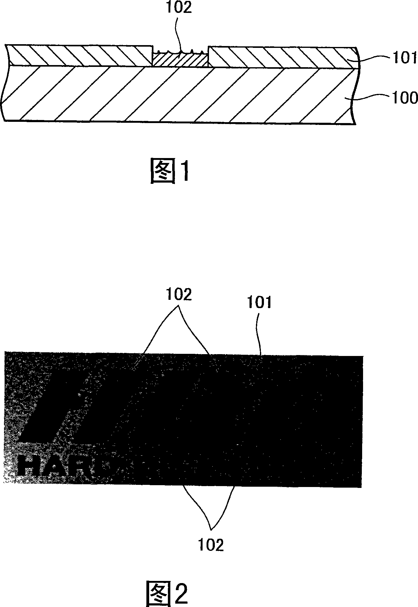
The laser beam irradiated portion 102 of the coating 101 has a rough surface due to the ablated carbon, so the result of the printed product exhibits poor print quality
If the carbon in a large part of the material is ablated, the material color itself may change so that the set color does not appear correctly in the printed product

Method used


Image

  • Coated-product with marking, process for manufacturing the same, and enclosure for electronic apparatus
  • Coated-product with marking, process for manufacturing the same, and enclosure for electronic apparatus
  • Coated-product with marking, process for manufacturing the same, and enclosure for electronic apparatus

Examples


example 1

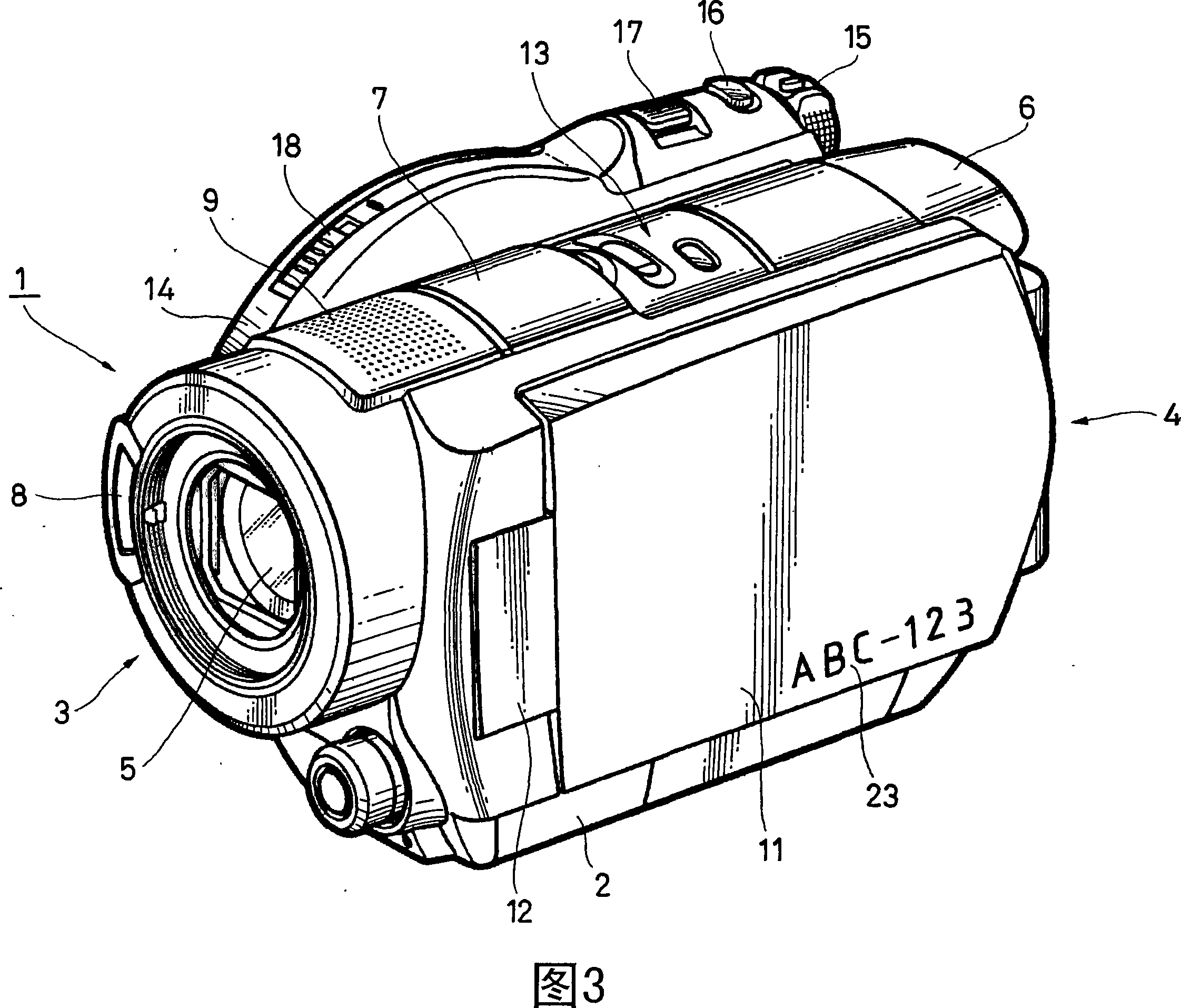
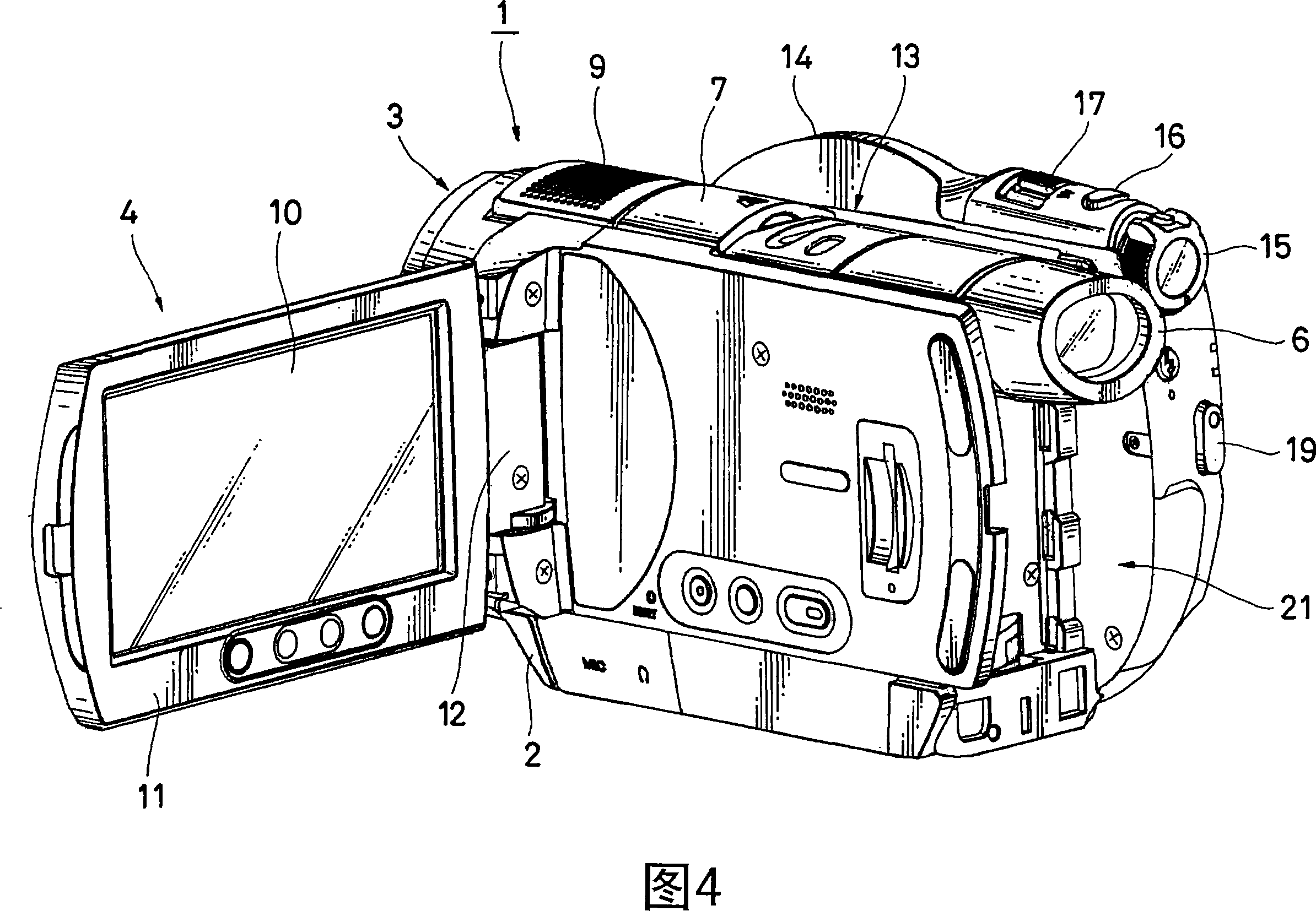
[0034]Specifically, an image forming apparatus having an electronic apparatus according to a first embodiment of the present invention with a coated product with a mark will be described below with reference to FIGS. 3 and 4 . The devices shown in FIGS. 3 and 4 represent digital camcorders 1 according to embodiments of imaging devices, respectively. The digital camcorder 1 employs an optical disc as an example of an information storage medium. In the digital camcorder 1, an optical image is converted into an electronic signal using an imaging element such as a charge-coupled device (CCD) or a CMOS image sensor as an example of an imaging mechanism, thereby recording the image signal on an optical disc or This information is displayed on a display device such as a liquid crystal display (LCD) formed of a flat panel.

[0035] However, the information storage medium used in the imaging device as an example of the electronic device of the present invention is not limited to an op...


PUM

PropertyMeasurementUnit
wavelengthaaaaaaaaaa

Abstract

Disclosed is a coated-product with marking. The coated-product is obtained by the steps of forming a coating layer having brightness higher than the brightness of a bare surface of a molding on the surface of the molding made of resin colored with dye, and removing a predetermined portion of the coating layer by laser marking and exposing the bare surface of the coated-product to form a marking portion.

Description

[0001] Related Application Cross Reference [0002] The present invention contains subject matter related to Japanese Patent Application JP 2006-346244 filed in the Japan Patent Office on Dec. 22, 2006, the entire content of which is hereby incorporated by reference. technical field [0003] The present invention relates to a coated product having a mark such as characters, numerals, graphics or patterns, a method of manufacturing the marked coated product, and a case for electronic equipment using the marked coated product. Background technique [0004] Examples of laser marking techniques are disclosed below. For example, Japanese Unexamined Patent Application Publication No. H8-132258 discloses a method of forming a laser mark by irradiating a marking portion such as characters, symbols, and figures with a laser beam, and a marking paper used for the method. The method disclosed in this patent application publication includes "irradiating to remove a predetermined porti...

Claims


Application Information

Patent Timeline
Patent Type & Authority Applications(China)
IPC IPC(8): B32B33/00B41M5/24B05D1/32B23K26/00B41M5/26
CPCB41M5/24Y10T428/239Y10T428/24802
Inventor 长井将刚
Owner SONY CORP
Learn More