Fan and frame thereof

A fan and fan frame technology, applied in the field of high-efficiency and low-noise fans and fan frames, can solve problems such as poor efficiency

Active Publication Date: 2011-04-20
DELTA ELECTRONICS INC
View PDF8 Cites 0 Cited by
  • Summary
  • Abstract
  • Description
  • Claims
  • Application Information

AI Technical Summary

Problems solved by technology

[0004] Therefore, in order to solve the above problems, the present invention proposes a fan and its fan frame. By arranging a plurality of flow guides on the stator blades, the flow direction of the airflow can be corrected and the flow guide area can be effectively increased to achieve rectification. Effect, thereby improving the overall efficiency of the fan, and improving the shortcomings of traditional fans with poor efficiency

Method used


Image

  • Fan and frame thereof
  • Fan and frame thereof
  • Fan and frame thereof

Examples


Embodiment Construction

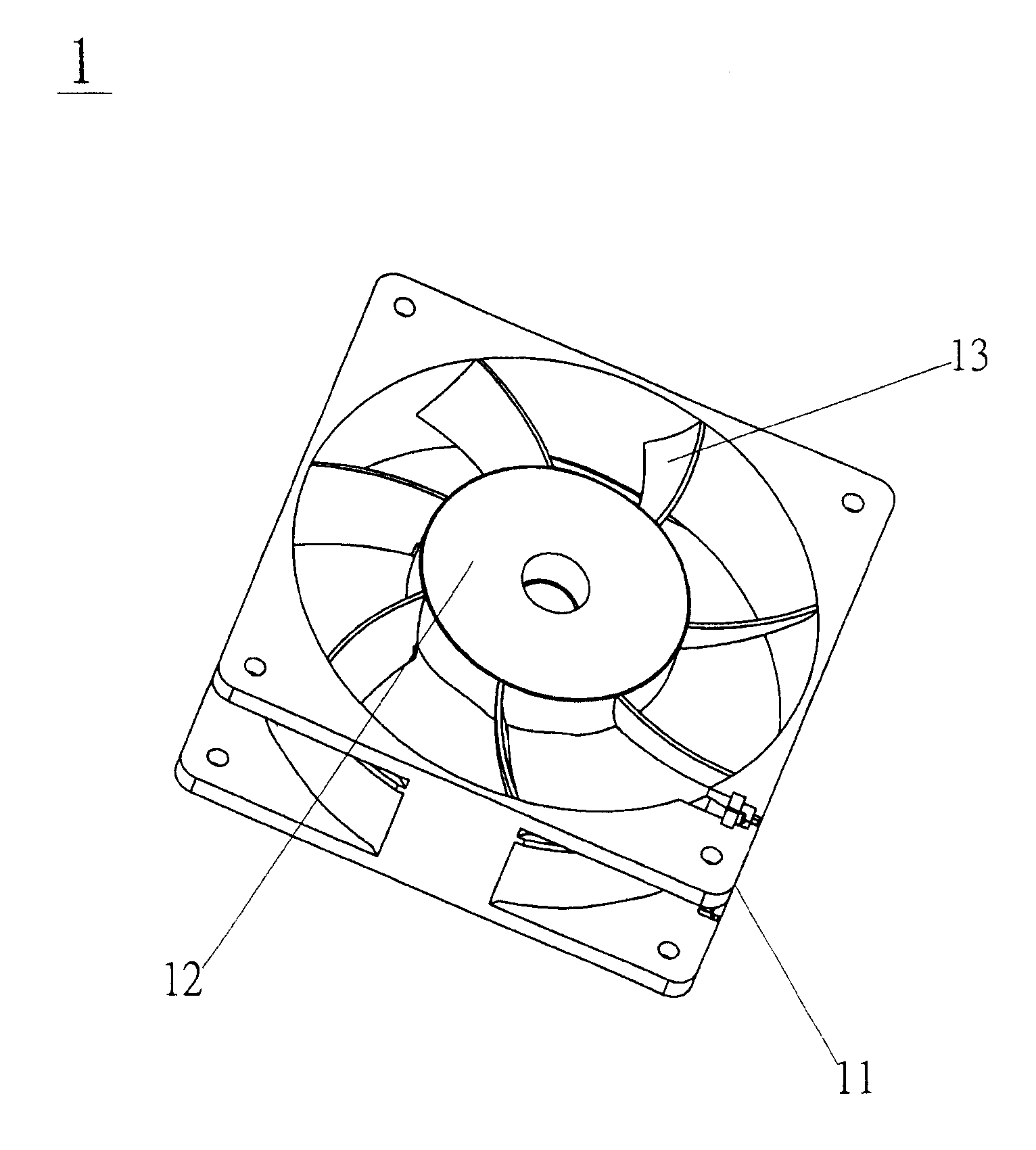
[0026] Please also refer to figure 2 , figure 2 It is a schematic diagram of a fan according to a preferred embodiment of the present invention. The fan 2 includes a fan frame 20, a motor 25 and an impeller 26. The fan frame 20 includes a main body 21, a motor base 22, a plurality of stator blades 23 and a plurality of air guides 24. The impeller 26 includes a hub 28 and a plurality of fan blades 27, and the fan blades 27 are arranged around the periphery of the hub 28. The motor base 22 is arranged in the main body 21 and is connected to the main body 21 by the stator blade 23. The shape of the main body 21 is roughly square, round, oval, polygonal, cone or other shapes. The impeller 26 is located in the main body 21 and is supported by the motor base 22. The motor 25 is arranged on the motor base 22 as a driving component to drive the impeller 26 to rotate.

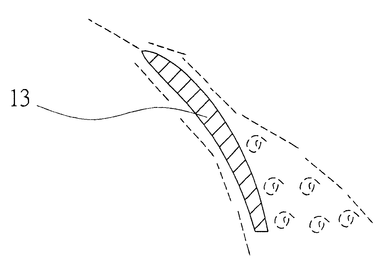
[0027] Continuing, please also refer to Figure 3A , Figure 3B versus Figure 4 , Figure 3A for figure 2 Schemati...


PUM


Abstract

The invention provides a fan which comprises a fan frame and an impeller, wherein, the fan frame is provided with a body, a motor base, a plurality of stator blades and a plurality of guide components, wherein, the impeller is positioned in the body of the fan frame, and carried on by the motor base; the motor base is arranged in the body, and connected with the body by the stator blades; each stator blade is provided with a first curved surface and a second curved surface; the guide components are respectively arranged on the first curved surfaces and the second curved surfaces of the statorblades, and respectively extended from the first curved surfaces and the second curved surfaces, wherein, the plurality of guide components are arranged on each stator blade with symmetrical type or staggered type. The invention can improve the wind pressure of the fan and the characteristics of a control region, can effectively improve the characteristics of a stalled area, and can reduce the noise generated by turbulent current.

Description

technical field [0001] The invention relates to a fan and its fan frame, in particular to a high-efficiency and low-noise fan and its fan frame. Background technique [0002] With the continuous improvement of the performance of electronic devices, cooling devices or cooling systems have become one of the indispensable equipment in current electronic devices, because if the heat energy generated by electronic devices is not dissipated properly, the performance will deteriorate at least, and the serious It may cause burning of the electronic device. Heat dissipation devices are even more important for microelectronic components (such as integrated circuits, integrated circuits), because with the increase in integration and the advancement of packaging technology, the area of ​​integrated circuits is continuously shrinking, and the heat energy accumulated per unit area It will also be relatively higher, so heat dissipation devices with high heat dissipation efficiency have al...

Claims


Application Information

Patent Timeline
Patent Type & Authority Patents(China)
IPC IPC(8): F04D29/54F04D25/06
Inventor 洪雅惠谢明凯林丽真陈怡玲
Owner DELTA ELECTRONICS INC
Why Eureka
Try Eureka