
Method for gluing conveyer belt joint

A conveying belt and gluing technology, applied in belt fasteners, belts/chains/gears, mechanical equipment, etc., can solve the problems of influence, long production time, long time, etc., to increase the roughening process and prolong the use. The effect of longevity, tool simplicity

Inactive Publication Date: 2008-06-25
YANKUANG LUNAN CHEM FERTILIZER PLANT
View PDF0 Cites 22 Cited by
  • Summary
  • Abstract
  • Description
  • Claims
  • Application Information

AI Technical Summary

Problems solved by technology

However, the existing cold-bonded belt gluing method takes a long time, and the gluing work of the belt should be completed during the overhaul stop time of the conveying system.
When the conveyor belt breaks during the operation of the conveyor system and needs to be glued, it will affect the long production time

Method used


Image

  • Method for gluing conveyer belt joint

Examples


Embodiment Construction

[0019] The bonding length at both ends is taken as 0.9-1.5 times the width of the conveyor belt. Take a conveyor belt with a width of 650mm as an example to illustrate the bonding method. The conveyor belt has five layers of canvas.

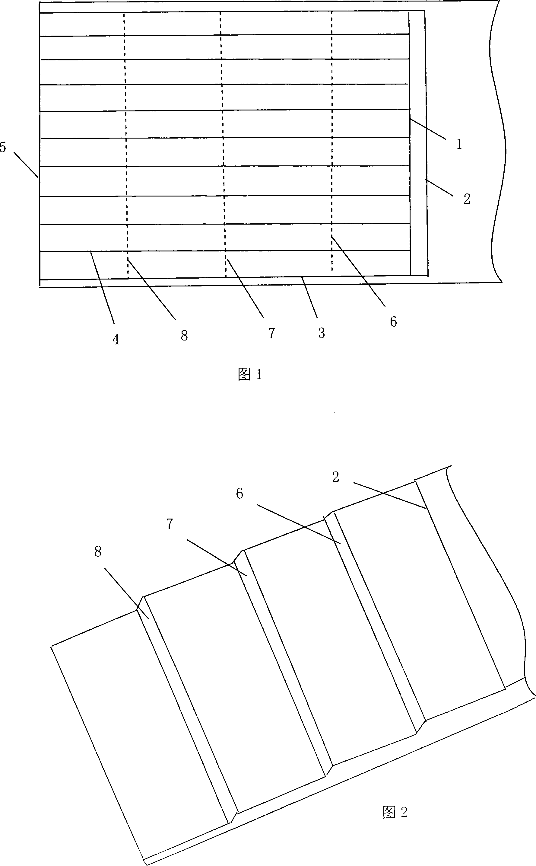
[0020] (1) draw a line, as shown in Figure 1

[0021] First, draw two inner horizontal lines 2 and outer horizontal lines 1 with a distance of 8-10mm parallel to the end surface at a distance of about 600mm from the end surface 5 of the conveyor belt. Draw a border line 3 between the lines 2, and draw a vertical line 4 between the end face 5 and the outer horizontal line 1 every 50 mm from the border line. The purpose of drawing the border line is because the rubber layer, not the canvas layer, is between the side of the conveyor belt and the border line.

[0022] (2) cutting and stripping, as shown in Figure 2

[0023] a Cut off the first layer of canvas along the inner horizontal line 2, outer horizontal line 1 and two border lines 3, and use...


PUM


Abstract

The invention provides a glue joint method of conveying belt lacer, which comprises the following steps: (1) wiping out line frames of braided fabric layers for glue joint at the head end and tail end of the conveying belt which need cutting off; (2) cutting and stripping the braided fabric layers for glue joint at the head and tail end of the conveying vertically and section by section from inside to end face along marking lines to form two ladder type glue joint faces where the number of the braided fabric layers gradually increases from end face to inside; (3) roughening and cleaning the ladder type glue joint faces; (4) brushing 2 rubber films with equal thickness and uniformity onto each roughened ladder type glue joint faces; (5) drying the ladder type glue joint faces on the two ends of the conveying belt until the two faces are not sticky to hands, sticking the two faces together and compacting; (6) trimming edges; (7) neatening. The invention gets rid of the prior tools for jacking and etc., adds a roughening procedure, and shortens the glue joint time of the conveying belt. The glue joint operation can be completed at a feeding interval of a conveying system with joint strength being greatly improved and the service life of the conveying belt being prolonged.

Description

technical field [0001] The invention relates to a glue bonding method for conveyor belt joints. Background technique [0002] Conveyor belts consist of multiple layers of braided fabric (canvas or nylon) covered with a layer of rubber. In practical application, the end of the conveyor belt should be connected together to form a closed loop. The quality of the end-to-end connection of the conveyor belt directly affects the safety and stability of the conveyor system. According to different running time, tensile strength, operating environment temperature, sealing requirements, etc., the current end-to-end connection methods of conveyor belts include mechanical connection method, cold bonding method and hot bonding method: [0003] 1. Mechanical connection method: by setting metal buckles on the two joints at the beginning and end of the conveyor belt, and inserting pins into the metal buckles, the two ends of the conveyor belt are connected. It is characterized by simple o...

Claims


Application Information

Patent Timeline
Patent Type & Authority Applications(China)
IPC IPC(8): F16G3/10
Inventor 郭晶陈凡光张元新陈爱中
Owner YANKUANG LUNAN CHEM FERTILIZER PLANT
Learn More