Eureka AIR delivers breakthrough ideas for toughest innovation challenges, trusted by R&D personnel around the world.

Method and device for monitoring plasma generator cathode life

A plasma and monitoring device technology, applied in the field of cathode life monitoring of plasma generators, can solve problems such as unit loss, and achieve the effect of convenient replacement

Inactive Publication Date: 2008-06-25
YANTAI LONGYUAN POWER TECH
View PDF0 Cites 5 Cited by
  • Summary
  • Abstract
  • Description
  • Claims
  • Application Information

AI Technical Summary

Problems solved by technology

Otherwise, it will bring immeasurable losses to the entire unit

Method used

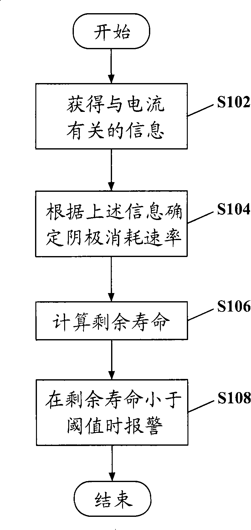
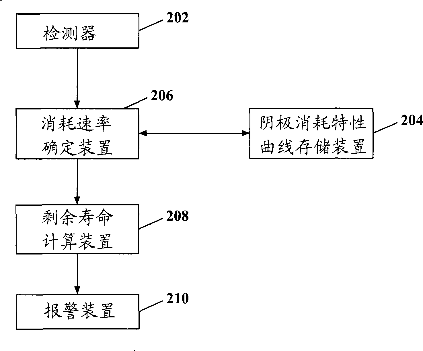

Image

  • Method and device for monitoring plasma generator cathode life
  • Method and device for monitoring plasma generator cathode life

Examples


Embodiment Construction

[0016] Specific embodiments of the present invention will be described in detail below in conjunction with the accompanying drawings.

[0017] The basic working principle of the plasma ignition device is electrode contact arc ignition, that is, after the cathode contacts the anode, a specific DC power supply is used to increase the current to the cathode and anode, and when the cathode leaves the anode, the arc is ignited, and at the same time, the arc is ignited by the magnetic force of the coil. Pulled out of the nozzle, the compressed air is ionized into high-temperature plasma under the action of the arc, forming a plasma arc. The plasma arc ignites the boiler soot.

[0018] According to the working principle of the plasma arc, the cathode is the high-temperature part of the plasma generator that emits electrons, and the burning loss is the working characteristic of the electrode. There are many factors that affect the service life of the cathode, among which the main fac...


PUM


Abstract

The invention relates to a cathode life monitoring method and device for a plasmatron, wherein, the method includes the following steps: related information of the electric current passing through a plasmatron cathode is obtained; according to the electric current, the consumption rate of the cathode is determined; moreover, according to the consumption rate, the residual life of the cathode is calculated. According to the invention, the residual life of the cathode can be predicted; therefore, the plasmatron cathode can be replaced in time.

Description

technical field [0001] The invention relates to a plasma generator cathode life monitoring method and device. Background technique [0002] The ignition and low-load stable combustion of traditional industrial pulverized coal boilers rely on fuel oil. In 1999, the fuel consumption of pulverized coal boilers in the national power system reached 287 tons, or nearly 10 billion yuan. Since the 1980s, experts from various countries have devoted themselves to the research of using plasma technology to directly ignite pulverized coal to save fuel. [0003] In the plasma ignition boiler, the plasma generator is used to generate high-temperature plasma through arc discharge, thereby igniting the coal powder. [0004] However, with the widespread use of plasma ignition devices in the field, some problems of plasma ignition devices have also been exposed. Among them, the service life of the burnt part cathode in the plasma generator is short, and the service life of the cathode canno...

Claims


Application Information

Patent Timeline
Patent Type & Authority Applications(China)
IPC IPC(8): G01R19/00
Inventor 唐宏薛若连李本伟郑庆元
Owner YANTAI LONGYUAN POWER TECH
Why Eureka
Eureka Blog
Learn More