Direct current speeder suitable for high power DC electric machine

A DC motor, DC speed regulation technology, applied in the direction of excitation or armature current control, can solve the problems of high price and high use cost, and achieve the effect of simple method, low cost, and expansion of excitation current

Inactive Publication Date: 2008-06-25
上海欧达电气成套设备工程有限公司 +1
View PDF0 Cites 0 Cited by
  • Summary
  • Abstract
  • Description
  • Claims
  • Application Information

AI Technical Summary

Problems solved by technology

Although there are ready-made DC speed controllers suitable for high

Method used


Image

  • Direct current speeder suitable for high power DC electric machine

Examples


Example Embodiment

[0008] The present invention will be further described below with reference to the accompanying drawings and embodiments.

[0009] This embodiment is improved by using the British Continental 590C type 35A DC speed regulating device.

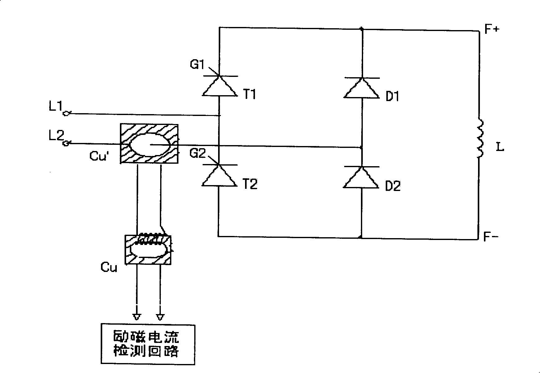
[0010] The DC speed regulating device of this embodiment includes an excitation part, an armature voltage part, a control part, and an alarm part. Among them, the excitation part such as figure 1 As shown, it consists of primary transformer Cu', secondary transformer Cu, thyristor G1, G2, diodes D1, D2 and excitation winding L. Among them, the semi-controlled bridge rectifier circuit composed of thyristors T1, T2, diodes D1 and D2 is built with German Siemens modules SKKT92B16E and SKKD100 / 16E; the ratio of primary current to secondary current of primary transformer Cu' is 60A to 5A , the incoming wire of the secondary transformer Cu is wound for 6 turns, and the secondary lead of the primary transformer Cu' is wound on Cu for 6 turns. When th...


PUM


Abstract

The invention provides a DC velocity modulation device that is applicable to a large-power DC motor. The device consists of an excitation part, an armature-voltage part, a controlling part and an alarming part, wherein, the excitation part consists of a circuit module, an excitation winding and a mutual-inductor. The invention is characterized in that the mutual-inductor comprises a primary mutual-inductor Cu1 and a secondary mutual-inductor Cu; the circuit module comprises a half-controlled bridge rectification circuit that is composed of a controllable silicon and a diode. The invention adopts the secondary mutual inductance method to enlarge the excitation current of the DC velocity-modulation device according to the principle of the transformer, thereby having simple method and low cost.

Description

technical field [0001] The invention relates to motor speed regulation technology, in particular to a DC speed regulation device suitable for high-power DC motors. Background technique [0002] Metallurgy and other industries often use high-power DC motors. The excitation current of these DC motors is relatively large, and some even reach dozens of amperes. The device cannot meet the usage requirements. Although there are ready-made DC speed regulators suitable for high-power DC motors on the market, they are expensive and costly to use. Contents of the invention [0003] The purpose of the present invention is to provide a DC speed regulating device which is improved on the basis of the existing small and medium power DC speed regulating device and can meet the requirements of high-power DC motor. [0004] To achieve the above object, the present invention adopts the following technical solutions: [0005] The DC speed control device suitable for high-power DC motors i...

Claims


Application Information

Patent Timeline
IPC IPC(8): H02P7/06H02P7/30
Inventor 陈广达王国阳
Owner 上海欧达电气成套设备工程有限公司
Why Eureka
Try Eureka