
Straight amplification station for self-adapting eliminating self excitation disturbance

An adaptive, repeater technology, applied in the field of mobile communications, can solve problems such as base station control channel blockage, base station paralysis, and impact on repeater system coverage, and achieve the effect of improving system gain and increasing coverage

Active Publication Date: 2008-06-25
COMBA TELECOM SYST CHINA LTD
View PDF0 Cites 8 Cited by
  • Summary
  • Abstract
  • Description
  • Claims
  • Application Information

AI Technical Summary

Problems solved by technology

[0003] However, in practical applications, since the front and rear antennas of the same-frequency wireless repeater are installed near each other, coupling will inevitably occur. If the system gain is too large, it is greater than the isolation between the front and rear antennas of the repeater. , the repeater will have self-oscillation, causing the control channel of the base station to be blocked, and even cause the base station to be paralyzed
[0004]In the same-frequency wireless repeater system, the interference source formed by the feedback signal will lead to the decline of the performance of the receiver system, and then make the same-frequency wireless repeater The system gain of the station is usually about 10-15dB lower than the isolation between the transmitting antenna and the receiving antenna, which will affect the coverage of the repeater system
In order to increase the system gain of the same-frequency wireless repeater, it is necessary to increase the isolation between the transmitting and receiving antennas, which forms a contradiction with the above, and is usually difficult to achieve in engineering applications

Method used


Image

  • Straight amplification station for self-adapting eliminating self excitation disturbance
  • Straight amplification station for self-adapting eliminating self excitation disturbance
  • Straight amplification station for self-adapting eliminating self excitation disturbance

Examples


Embodiment Construction

[0046] Below in conjunction with accompanying drawing and embodiment the present invention will be further described:

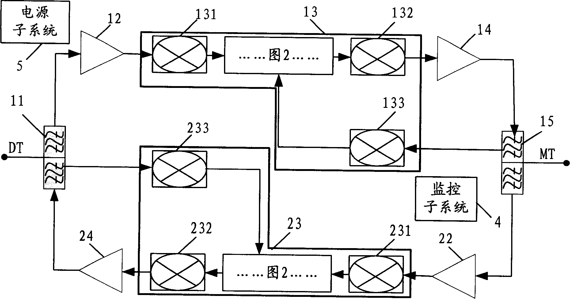
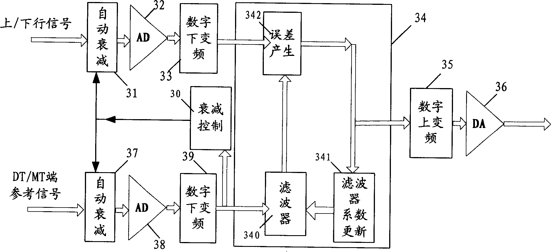
[0047] Please combine figure 1 and figure 2 , figure 1 It is the principle block diagram of self-adaptive elimination self-excited interference repeater of the present invention, figure 2 It is the functional block diagram of the anti-self-excitation module of the present invention, but the analog down-converter is in figure 1 shown in .

[0048] figure 1 Among them, the downlink is composed of the DT end duplexer 11, the downlink amplification modules 12, 14, the downlink anti-self-excitation module 13, and the MT end duplexer 15, and the MT end duplexer 15, the uplink amplification modules 22, 24, The uplink anti-self-excitation module 23 and the DT-side duplexer 11 together constitute an uplink.

[0049] Wherein, the uplink and downlink amplifying modules 22, 24, 12, 14 can be low noise amplifying modules 12, 22 or power amplifying modules 14, 24, ...


PUM


Abstract

The invention discloses a self-adapting self-excitation interference eliminating repeater, which comprises: two duplexers, which are respectively communicated with a donor antenna and a spot beam antenna, and are used for the switch between the up-link and down-link; two amplifier modules, which are arranged between two duplexers and are respectively used for forming the up-link and down-link, and used for amplifying the power or filtering the noise respectively for the up-link and down-link signals; moreover, the up-link and / or down-link are provided with a self-excitation preventing module, used for eliminating the self-excitation component produced by the antenna at the output terminal within the RF signal of the link. The shared-channel radio repeater of the invention effectively eliminates the self-excitation produced by the feedback signal in a self-adapting way, thereby the requirement for the isolation of the forward, backward antennas is decreased; and the system gain is raised. The invention is suitable for the SM / CDMA / CDMA2000 / WCDMA mode repeaters, and can be applied to TD-SCDMA repeater system and digital television system, etc. through proper improvement.

Description

【Technical field】 [0001] The invention relates to the field of mobile communication, in particular to a repeater for self-adaptive elimination of self-excited interference among co-frequency wireless repeaters. 【Background technique】 [0002] The same-frequency wireless repeater usually uses a duplexer to switch between the uplink and downlink, uses the forward antenna to receive the downlink signal of the base station, amplifies the useful signal through a low-noise amplifier, and then uses a narrowband filter to further filter the downlink signal with a power amplifier. The power is amplified and transmitted to the mobile station by the backward antenna; at the same time, the uplink signal of the mobile station is received by the backward antenna, and transmitted to the base station through a low noise amplifier, a narrowband filter, and a power amplifier. Its advantages are: to expand the coverage area at a cost far lower than the base station investment, the installation...

Claims


Application Information

Patent Timeline
IPC IPC(8): H04Q7/30H04B7/14
Inventor 赖文强刘志敏罗漫江
Owner COMBA TELECOM SYST CHINA LTD
Learn More