Self-cleaning reinforcement heat transfer low flow resistance rotor in heat-transfer pipe

A technology for enhancing heat transfer and heat transfer tubes, which is applied in the direction of heat transfer modification, cleaning of rotating equipment, cleaning of heat transfer devices, etc. Complicated structure and other issues, to achieve the effect of reducing raw material consumption, improving performance and reducing friction

Inactive Publication Date: 2008-07-02
山西英蓝科技有限公司
View PDF1 Cites 16 Cited by
  • Summary
  • Abstract
  • Description
  • Claims
  • Application Information

AI Technical Summary

Problems solved by technology

The main disadvantages of the spiral bond are: 1) a large driving torque is required during the working process; 2) the bond directly scrapes the inner wall of the heat transfer tube; 3) the service life of the end rotating bearing is short
4) In addition to the automatic descaling effect, the effect of field synergy enhanced heat transfer is not significant; Chinese Patent No. ZL200520127121.9 discloses a patent application entitled "Rotor Type Self-cleaning Enhanced Heat Transfer Device", which consists of a fixed frame, Composed of rotor, flexible shaft and support tube, two fixed frames are respectively fixed at both ends of the heat transfer tube; the outer surface of the rotor has screw edges, and the rotor has a central hole; the support tube is set between the rotor and the fixed frame, and the flexible shaft passes through The central hole of the rotor and the support tube are fixed on the two fixed frames
However, because its structure is a continuous screw flight design, when the cooling medium flows in the heat transfer tube, under the working condition of a certain flow rate, the rotation speed of the rotor is determined by the helix angle of the screw flight. Smaller, that is, the shorter the screw lead, the faster the rotor rotates, but at the same time its flow resistance also increases
When the rotation speed of the rotor is high, for example, above 200 rpm, the fluid in the heat transfer tube will cause turbulent flow under the disturbance of the screw edge, and the effect of enhancing heat transfer is remarkable. However, the problem of increased flow resistance is also very prominent. The test shows that in a heat transfer tube with a length of 8 meters and a diameter of 23 mm, the heat transfer tube with a triangular rotor with a lead of 100 mm is compared with the light tube, and the flow area is reduced at the same power pumping. conditions, the flow rate is reduced by more than 50%
Although the problem of increased flow resistance can be alleviated to a certain extent by opening holes on the screw edge, it brings a series of problems such as complex mold structure, increased manufacturing cost, and shortened service life to the molding process.

Method used


Image

  • Self-cleaning reinforcement heat transfer low flow resistance rotor in heat-transfer pipe
  • Self-cleaning reinforcement heat transfer low flow resistance rotor in heat-transfer pipe
  • Self-cleaning reinforcement heat transfer low flow resistance rotor in heat-transfer pipe

Examples


Embodiment Construction

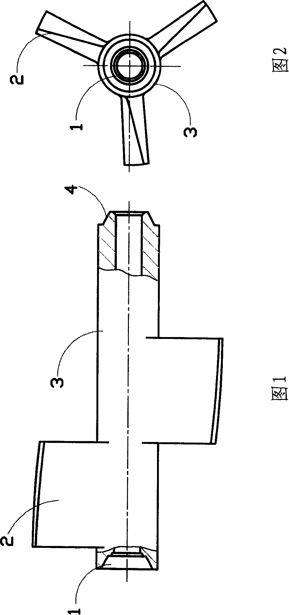
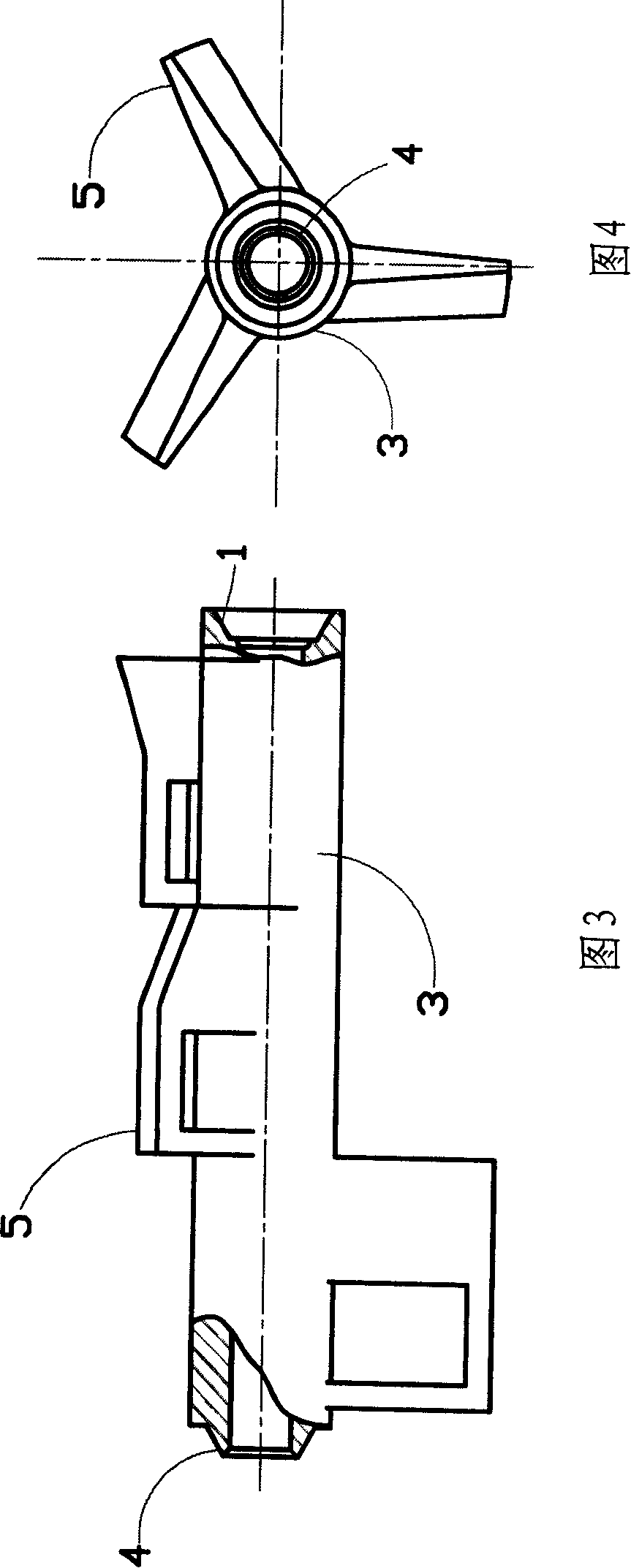
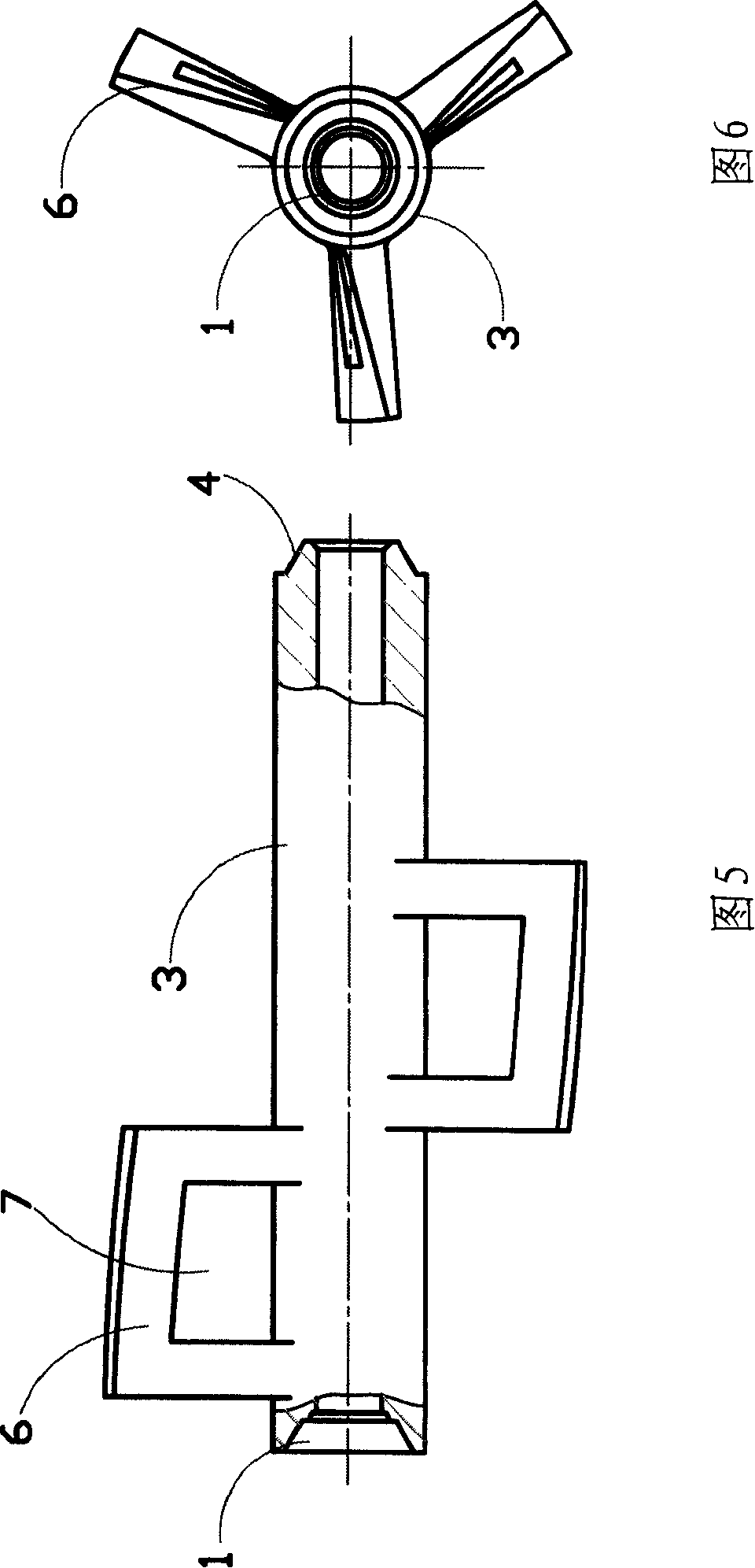
[0024] As shown in Figure 8, an embodiment of the self-cleaning low-flow resistance rotor in the heat transfer tube of the present invention, which includes a rotor, a support frame 8 and a connecting axis 11, and the support frame 8 is fixed on the heat transfer tube The two ends of the pipe 10 and the two ends of the connection axis 11 are respectively fixed on the support frame 8, and the several rotors are mounted on the connection axis 11 between the two support frames 8, and the rotors are composed of the hollow shaft 3 and the working surface. It is composed of scroll fins 2 in a spiral shape, and more than one scroll fins 2 are arranged on the hollow shaft 3, and each scroll fin 2 is inclined to the center line of the hollow shaft 3, and each A scroll fin 2 is evenly fixed on the outer surface of the hollow shaft 3 .

[0025] Each adjacent fin 2 rotates around the hollow shaft 3 as the center, and the space swept by it is connected back and forth.

[0026] As shown in...


PUM


Abstract

The invention relates to a low-flow resistance rotor with self-cleaning function and heat transfer enhancement used in a heat transfer tube, which comprises a plurality of rotors, supporting frames and a connecting shaft line. The supporting frames are fixed at the two ends of the heat transfer tube. The two ends of the connecting shaft line are fixed on the supporting frames respectively. The plurality of rotors are skewered on the connecting shaft line between the two supporting frames. The rotor consists of a hollow shaft and fins, wherein the hollow shaft is provided thereon with one and more fin(s), each fin is oblique to the central line of the hollow shaft, the working surface of each fin is swirl or flat or a combination thereof, and the fins are fixed uniformly on the outer surface of the hollowing shaft. In the inventive technical proposal, a fluid inside a tube can drive the rotor by the fins to rotate at a proper speed, so as to inhibit and eliminate the deposition of dirt, the fins can disturb the fluid inside the tube to enhance the convection heat transfer, the rotor occupies a small area inside the heat transfer tube to increase the axial flow area and reduce the blockage rate and flow resistance in the heat transfer tube, and the service life of the rotor is significantly prolonged.

Description

technical field [0001] The invention relates to an interpolation element for anti-fouling and descaling and enhancing heat transfer in heat transfer tubes used in shell-and-tube heat exchangers, heat exchange reactors, etc. Self-cleaning low-flow resistance rotors in the heat transfer tubes enhance heat transfer. Background technique [0002] A large number of heat exchangers are used in the fields of thermal power, nuclear power, petroleum, chemical industry, metallurgy, food, light industry, ship power and aerospace, among which shell-and-tube heat exchangers account for the vast majority, but shell-and-tube heat exchangers The problem of fouling and fouling on the inner wall of heat transfer pipes of type heat exchangers is common, which reduces the heat transfer performance, increases the resistance of fluid transportation, and even causes pipe blockage; pipe wall fouling will not only bring safety hazards of corrosion and leakage , and cause serious energy waste due to...

Claims


Application Information

Patent Timeline
Patent Type & Authority Applications(China)
IPC IPC(8): F28G3/00F28F13/12
Inventor 殷淑桂孙广和
Owner 山西英蓝科技有限公司
Why Eureka
Try Eureka