Laser emission axis and mechanical base level coaxiality measuring method based on angle prism

A technology of coaxiality measurement and laser emission, which is applied in the field of measurement, can solve problems such as measurement, small beam divergence angle, pointing control accuracy, etc.

Inactive Publication Date: 2008-07-02
HARBIN INST OF TECH
View PDF0 Cites 17 Cited by
  • Summary
  • Abstract
  • Description
  • Claims
  • Application Information

AI Technical Summary

Problems solved by technology

[0003] In order to solve the problem that the angle between the laser emission axis and the mechanical reference plane needs to be strictly measured in an optical test system with small beam divergence angle and high pointing control precision, and there is no way to measure it at present, the present invention proposes A method for measuring coaxiality between laser emission axis and mechanical reference plane based on corner prism

Method used


Image

  • Laser emission axis and mechanical base level coaxiality measuring method based on angle prism

Examples


specific Embodiment approach 1

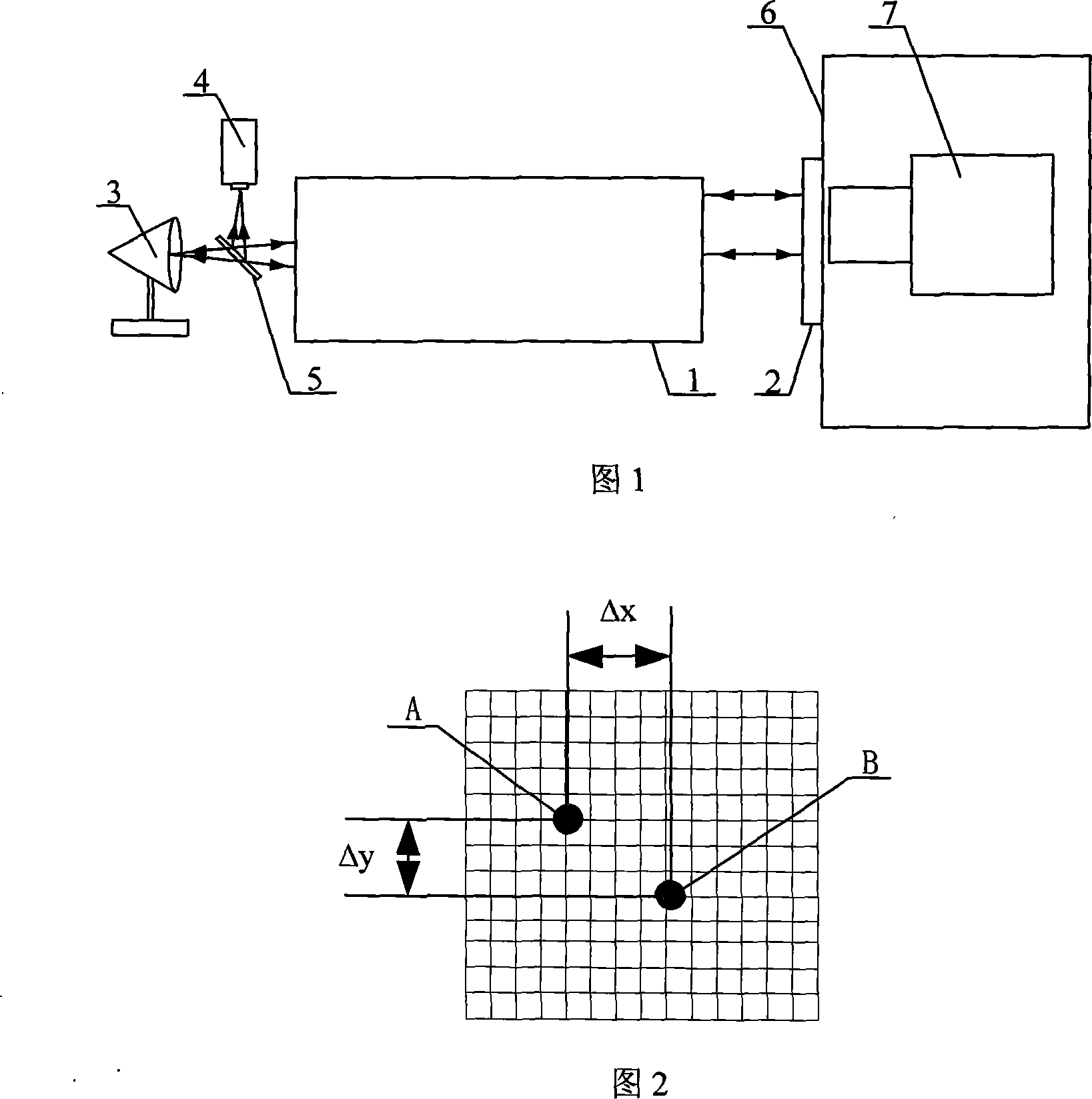
[0013] Specific Embodiment 1: This embodiment is described in conjunction with FIG. 1 , and the steps of this embodiment are as follows:

[0014] Step 1: Bond the reflective surface of the high-precision flat mirror 2 to the measured mechanical reference surface 6, so that the normal direction of the high-precision flat mirror 2 is parallel to the normal direction of the measured mechanical reference surface 6, and the high-precision flat mirror 2 blocks the laser emission system 7 light exit aperture, the working surface bonded to the measured mechanical reference surface 6 is coated with a semi-transparent and semi-reflective film with a reflectivity of 50%, and the opposite working surface is coated with an anti-reflection film;

[0015] Step 2: When measuring, the laser emission system 7 under test emits a laser beam, the laser beam is focused by the telephoto collimator 1, and after focusing, the measured laser beam is irradiated on the 1 between the light outlet and the f...

specific Embodiment approach 2

[0020] Embodiment 2: This embodiment differs from Embodiment 1 in that the telephoto collimator 1 has a focal length of 12 m and an aperture of 400 mm. Other components and steps are the same as those in Embodiment 1.

specific Embodiment approach 3

[0021] Embodiment 3: This embodiment differs from Embodiment 1 in that the high-precision plane mirror 2 is a plane mirror with a diameter of φ300, and the surface precision (RMS) is 1 / 70λ. Other components and steps are the same as those in Embodiment 1.


PUM


Abstract

An angle prism-based method is provided to measure the coaxiality between a laser emission shaft and a mechanical reference surface. The invention relates to the measurement field and solves the problems that no method is available for accurate measurement of the included angle between the laser emission shaft and the mechanical reference surface in an optical test system with small beam divergence angle and strict requirement for pointing control accuracy. The method comprises the following steps: firstly, the reflection surface of a high-precision planar mirror is adhered to the mechanical reference surface to be measured; then, the measurement is performed, wherein the laser beam is focused by a long-focal-depth collimator tube and exposed to a 1:1 light splitter on the long-focal-depth collimator tube, a half of the laser beam is reflected onto a CCD detector, enters the long-focal-depth collimator tube and is imaged on the CCD detector (4); and finally, the directional angle deviation (Alpha) and pitch angle deviation (Beta) between two light spots are calculated. The measurement accuracy of the inventive method is increased by 0.1 Murad.

Description

technical field [0001] The invention relates to the field of measurement, in particular to a method for measuring the coaxiality of a laser emission axis and a mechanical reference plane based on a corner prism. Background technique [0002] When installing the laser emission system on the mechanical support platform, it is required that the laser emission axis be precisely aligned with the normal line of the reference plane of the support platform, which requires high-precision coaxiality between the laser emission axis and the mechanical reference plane during the installation process. Measurement. At present, most optical systems do not have strict requirements on the angular difference between the optical axis and the mechanical axis, and do not need to accurately measure the difference between them. However, for an optical test system with a small beam divergence angle and high pointing control accuracy, the angle between the laser emission axis and the mechanical refe...

Claims


Application Information

Patent Timeline
Patent Type & Authority Applications(China)
IPC IPC(8): G01B11/26
Inventor 马晶谭立英刘剑峰韩琦琦于思源俞建杰杨玉强
Owner HARBIN INST OF TECH
Why Eureka
Try Eureka