Projection display device

A projection display and magnification device technology, which is applied in the direction of using projection device image reproducer, projection device, optics, etc., can solve the problems of high cost and large volume of projection display devices, and achieve space saving, simple optical path, and volume reduction Effect

Inactive Publication Date: 2008-07-02
INNOCOM TECH SHENZHEN +1
View PDF0 Cites 10 Cited by
  • Summary
  • Abstract
  • Description
  • Claims
  • Application Information

AI Technical Summary

Problems solved by technology

[0005] In order to solve the problem of high cost and large volume of the prior art projection display device, it is necessary to provide a projection display device with low cost and small volume

Method used


Image

  • Projection display device
  • Projection display device
  • Projection display device

Examples


Embodiment Construction

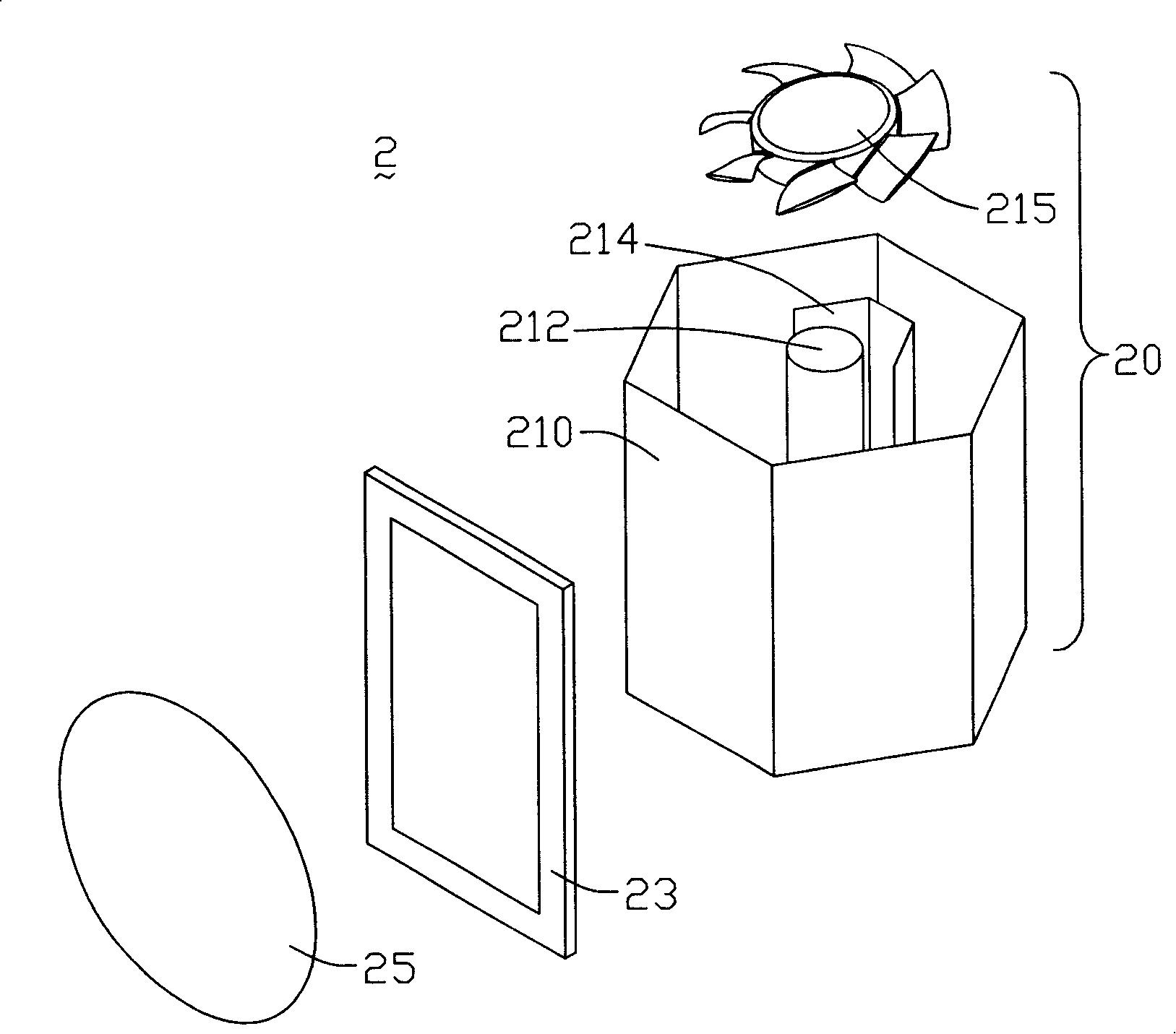
[0012] see figure 2 , is a schematic perspective view of the first embodiment of the projection display device of the present invention. The projection display device 2 includes a light source module 21 , a liquid crystal panel 23 , an image magnifying device 25 and a display screen (not shown). The liquid crystal panel 23 is controlled by a driving circuit to convert the monochromatic light beam projected thereon into an image with a certain monochromatic gray scale.

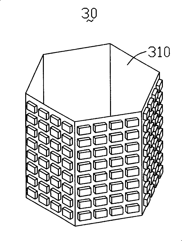
[0013] The light source module 20 includes a rotating multi-faceted structure 210, a light source 212, and a reflector 214. The rotating multi-faceted structure 210 has a plurality of faces around the central axis, and the number of the plurality of faces is a multiple of three. The surface is a unit, one side is provided with a red filter, one side is provided with a green filter, and the other side is provided with a blue filter, the light source 212 is located at the central axis of the rotating polyhedral...


PUM


Abstract

The invention relates to a projection display device, which comprises a light source module and a liquid crystal panel. The light source module comprises a rotating multi-surface structure and a light source, wherein the rotating multi-surface structure comprises multiple surfaces around a central axis, the number of the multiple surfaces is multiple of three, every three surfaces are one unit and are respectively provided with a red filter, a green filter and a blue filter. The light source is positioned at the central axis of the multi-surface structure. When the rotating multi-surface structure rotates around the central axis, light beams which are emitted by the light source respectively form red light, green light and blue light after being filtrated by the red filter, the green filter and the blue filter, then the lights are sequentially projected to the liquid crystal panel which converts the red light, the green light and the blue light respectively to an image with a certain single-color gray-scale according to image signals, and the image is output via an image amplification device.

Description

technical field [0001] The invention relates to a projection display device. Background technique [0002] LCD rear projection is the product of the combination of liquid crystal display technology and projection technology. It uses the photoelectric effect of liquid crystal to control the deflection direction of liquid crystal molecules by applying the voltage across the liquid crystal unit, thereby controlling the transmittance of light passing through the liquid crystal unit. , to produce images with different gray scales and colors. Generally, LCD rear projection adopts three-piece LCD panels, and the three LCD panels are respectively used as the control layer of red, green, and blue three-color light. That is, after the white light emitted by the light source passes through the color separation system, it is separated into red, green and blue three-color light. The arrangement changes under the action of an electric field, which affects the light transmittance or refl...

Claims


Application Information

Patent Timeline
Patent Type & Authority Applications(China)
IPC IPC(8): G03B21/14G03B21/16G03B21/00G02F1/13H04N9/31
Inventor 颜硕廷
Owner INNOCOM TECH SHENZHEN
Why Eureka
Try Eureka