Method for establishing electric impedance control line

An impedance control and impedance line technology, applied in special data processing applications, instruments, electrical digital data processing, etc., can solve the problems of labor-intensive time, increase process cost, etc., and achieve the effect of saving time, reducing labor, and good technology inheritance

Inactive Publication Date: 2008-07-02
INVENTEC CORP
View PDF0 Cites 4 Cited by
  • Summary
  • Abstract
  • Description
  • Claims
  • Application Information

AI Technical Summary

Problems solved by technology

[0005] The purpose of the present invention is to establish standardized impedance control lines and collect them into an impedance control line database t

Method used


Image

  • Method for establishing electric impedance control line
  • Method for establishing electric impedance control line
  • Method for establishing electric impedance control line

Examples


Embodiment Construction

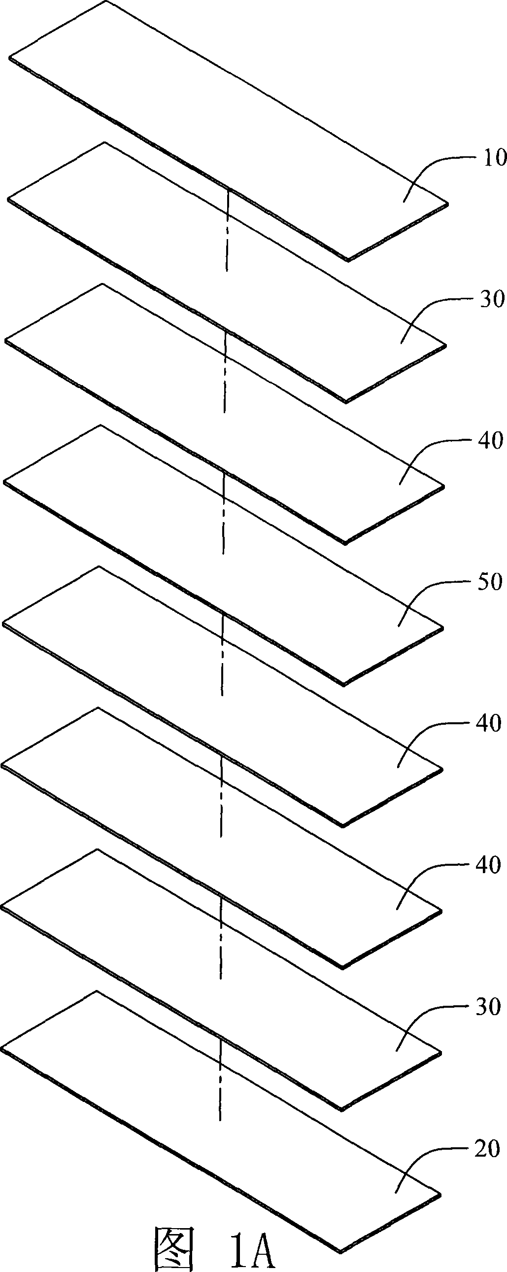
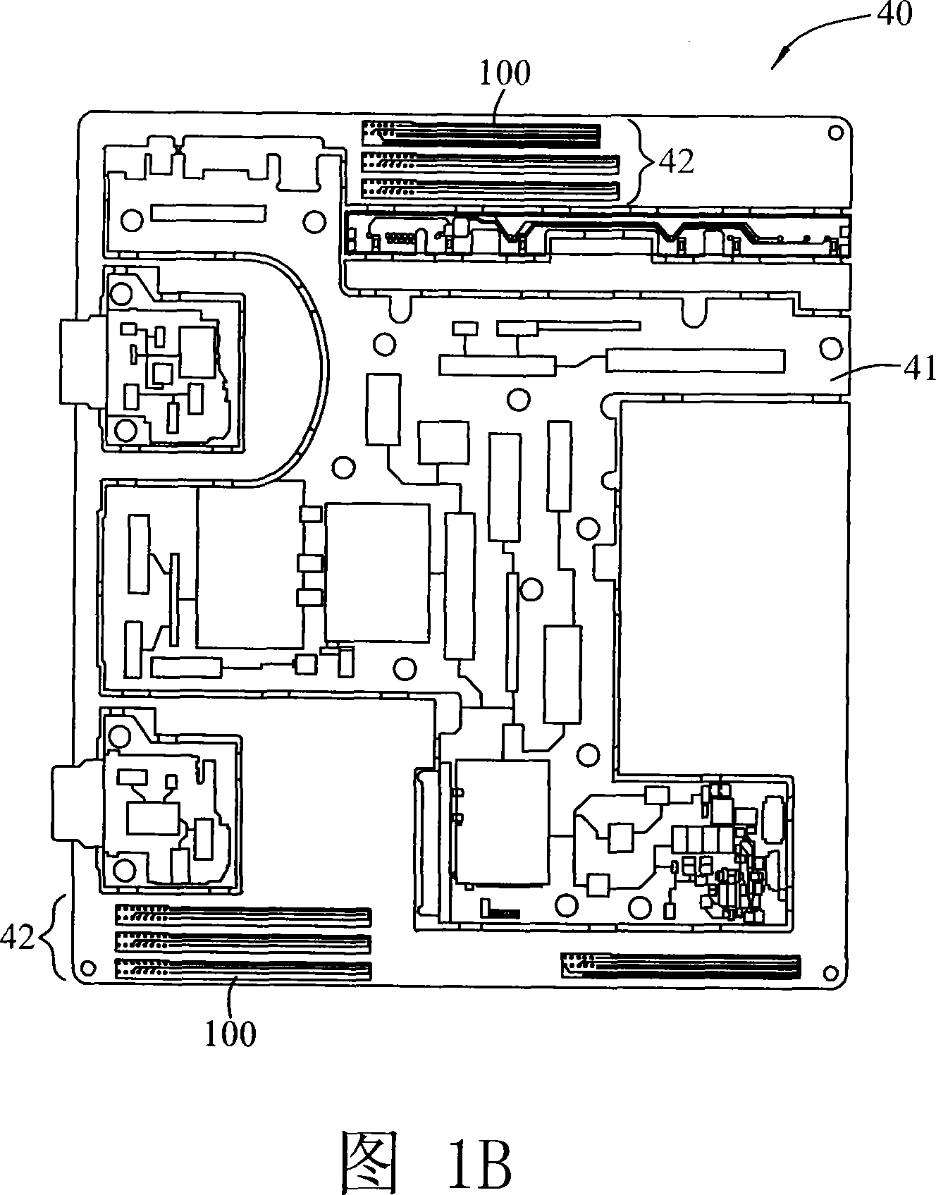
[0031] First, please refer to FIG. 1A and FIG. 1B , FIG. 1A is an exploded schematic diagram of a multilayer printed circuit board. FIG. 1B is a schematic diagram of a circuit board with impedance test leads. This embodiment takes an eight-layer printed circuit board as an example, which includes a top layer 10 , a bottom layer 20 , a plurality of ground layers 30 , a plurality of signal layers 40 and a power layer 50 . Each layer is provided with finely connected circuit wiring. As shown in FIG. 1B, in the present invention, taking a signal layer 40 as an example, the signal layer 40 has a circuit area 41 and a test area 42, and the circuit area 41 has circuit wirings that are finely connected to each layer, which is the signal layer 40. The main working area of ​​the circuit board, and the test area 42 is provided with a plurality of impedance control lines 100, which are commonly grounded with the circuit area 41, but are not directly electrically connected. When the circu...


PUM


Abstract

The invention discloses a method for establishing impendence control wires; the method is used in a multi-layered PCB. First of all, connect with a database for impendence control wires; the impendence control wire database stores a plurality of impendence control wires and a group of defined parameter values corresponding to all impendence control wires. Then, input a group of the parameter values that respectively include a layer of values, a board thickness value, a wire width value as well as a space value. After that, perform comparison between the input group of the parameter values and the defined parameter values in the impendence control wire database, so as to gain a group of defined parameter values that are complied with and corresponding impendence control wires. Moreover, arrange the acquired impendence control wires into a layer of the multi-layered PCB.

Description

technical field [0001] The invention relates to a circuit wiring method on a multilayer printed circuit board, in particular to a method for establishing impedance control lines (Coupon Bar) and its database (Coupon Bar Library) to facilitate effective circuit wiring. Background technique [0002] In recent years, due to the rapid development of electronic technology and semiconductor components, circuit design and provided functions have made great progress, and the industry is constantly developing towards higher-density wiring and multi-functional wiring design in circuit design. And cooperate with computer wiring software to achieve fast and simulated wiring technology. [0003] However, in the practice of wiring technology, relevant professionals use their personal skills to wire and measure whether the lines are connected correctly, which will consume a lot of manpower and a lot of time for wiring and debugging steps. Moreover, due to the increasing wiring density of ...

Claims


Application Information

Patent Timeline
IPC IPC(8): G06F17/50
Inventor 游巧毓郑永健蔡秋凤
Owner INVENTEC CORP
Why Eureka
Try Eureka