Switchable surface acoustic wave filter bank with two channel bandwidths

A surface acoustic wave and filter bank technology, which is applied in the direction of instruments, radio wave measurement systems, impedance networks, etc., can solve the problem that there are no switchable surface acoustic wave filter banks with two channel bandwidths, and achieve low insertion loss, The effect of low amplitude fluctuation and low squareness coefficient

Inactive Publication Date: 2008-07-02
INST OF ACOUSTICS CHINESE ACAD OF SCI
View PDF1 Cites 21 Cited by
  • Summary
  • Abstract
  • Description
  • Claims
  • Application Information

AI Technical Summary

Problems solved by technology

[0003] There is no switchable SAW filter bank with two channel bandwidths in the prior art

Method used


Image

  • Switchable surface acoustic wave filter bank with two channel bandwidths
  • Switchable surface acoustic wave filter bank with two channel bandwidths
  • Switchable surface acoustic wave filter bank with two channel bandwidths

Examples


Embodiment 1

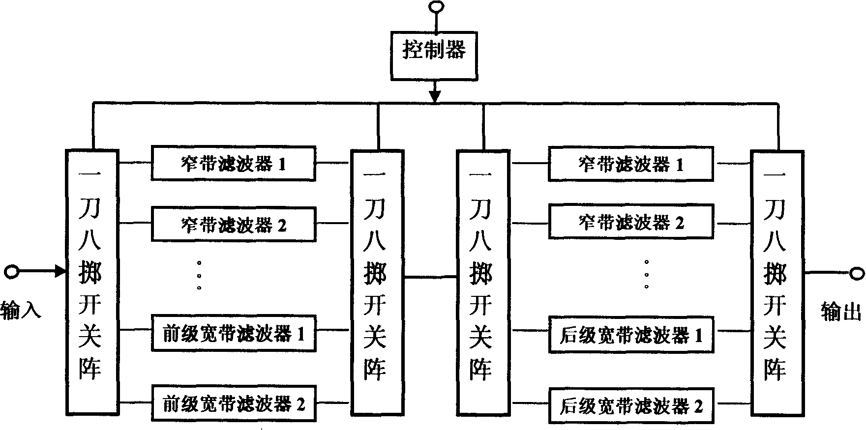
[0039] figure 2It is a functional block diagram of two kinds of channel bandwidth, low loss and high stopband suppression passive switchable surface acoustic wave filter bank of the present invention, which is composed of two sets of surface acoustic wave filters 3, four sets of one-knife-eight-throw switches 2 and a controller 1 . Controller 1 converts the external three-bit TTL signal into an 8-bit driving signal, and controls four sets of switches to switch simultaneously. At a certain moment, only one of the channels is turned on, and the other channels are turned off, and all the power of the input signal is added to the channel. , so there is no loss in the combined network. In this embodiment, the 1-pole, 8-throw switch is formed by parallel connection of one ends of eight 1-pole, 1-pole, 1-throw switches. The 1-pole, 1-throw switch is composed of a discrete component PIN diode circuit, and can also be made of an integrated circuit.

[0040] In this embodiment, the w...

Embodiment 2

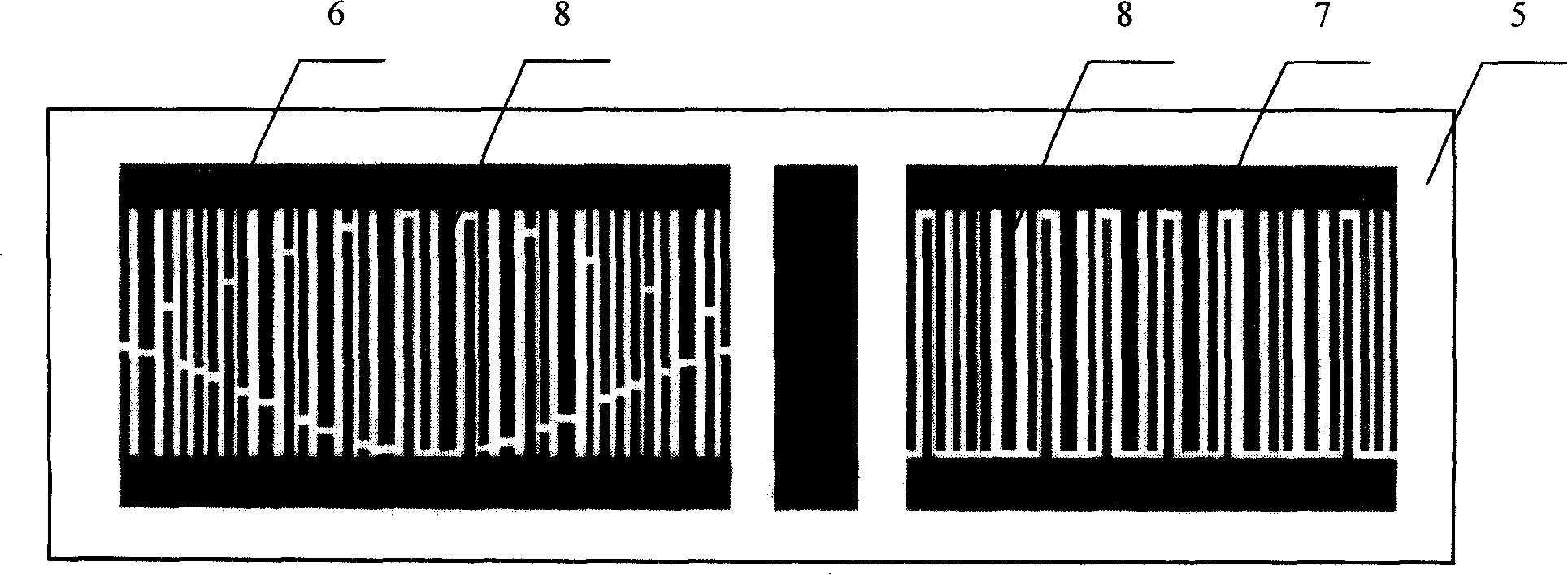
[0050] Compared with Embodiment 1, this embodiment has a different structure of the single-phase unidirectional transducer used in the narrowband channel. In this embodiment, the filter chip of the single-phase unidirectional transducer structure is such as Figure 4 As shown, the chip is composed of two finger-weighted transducers 7 on a piezoelectric substrate 5 .

[0051] In this embodiment, the ratio of the thickness of the reflective electrode metal grid bar to the wavelength of the single-phase unidirectional transducer structure filter in the narrowband channel is 1.2%.

[0052] In this embodiment, the ratio of the reflective electrode thickness to the wavelength of the fan-shaped transducer structure filter in the broadband channel is 1.4%.

[0053] The remaining parts in this embodiment are completely consistent with Embodiment 1.

Embodiment 3

[0055] Compared with Embodiment 1, this embodiment has a different structure of the single-phase unidirectional transducer used in the narrowband channel. In this embodiment, the filter chip of the single-phase unidirectional transducer structure is such as Figure 5 As shown, in this embodiment, the chip consists of abscissa weighted transducers 6 and unweighted transducers 9 on a piezoelectric substrate 5 .

[0056] In this embodiment, the ratio of the reflective electrode thickness to the wavelength of the single-phase unidirectional transducer structure filter in the narrowband channel is 1.6%.

[0057] In this embodiment, the ratio of the reflective electrode thickness to the wavelength of the fan-shaped transducer structure filter in the broadband channel is 1.8%.

[0058] The remaining parts in this embodiment are completely consistent with Embodiment 1.


PUM


Abstract

The invention relates to a switchable filter group of surface acoustic wave having two channel bandwidths, which comprises a multi-fling switch, a controller and a plurality of filters of surface acoustic wave and is characterized in that: a plurality of filters of surface acoustic wave form at least a narrow-band channel and a wide-band channel; the narrow-band channel comprises two concatenated filters of surface acoustic waves which both apply unidirectional transducer structures of single-phase made on quartz; the wide-band channel comprises two concatenated different filters of surface acoustic wave, wherein, a pre-stage filter of surface acoustic wave applies a vertical coupling structure of a resonate filter, and a last-stage filter of surface acoustic wave applies a structure of a sector filter. The invention can realize low insertion loss in the narrow-band channel and also realize low rectangle coefficient; at the same time, the invention can realize low insertion loss in the wide-band channel, high stopband rejection and low rectangle coefficient, and the insertion loss and the narrow-band channel are close to passing.

Description

technical field [0001] The invention relates to a switchable surface acoustic wave filter bank, in particular to a switchable surface acoustic wave filter bank with low loss and high stopband suppression which is applied in a phased array radar receiver and has two channel bandwidths. Background technique [0002] The switchable surface acoustic wave filter bank that can realize the program control function is needed for frequency hopping communication and frequency-agile radar: one is to select frequency in the frequency synthesizer; the other is to do anti-interference filtering in the receiver. In the application of the receiver, the received signal is generally very weak. In order to ensure the signal-to-noise ratio of the system, the filter bank is required to have a low insertion loss; in order to suppress strong interference signals, a single filter is required to have a narrow bandwidth, steep transition band and high stop band rejection. [0003] There is no switch...

Claims


Application Information

Patent Timeline
Patent Type & Authority Applications(China)
IPC IPC(8): H03H9/64G01S7/285
Inventor 何世堂李顺洲刘建生刘久玲
Owner INST OF ACOUSTICS CHINESE ACAD OF SCI
Why Eureka
Try Eureka