System for controlled delivery of stents and grafts

A vascular system and prosthesis technology, applied in the field of delivery devices

Inactive Publication Date: 2008-07-02
AGA MEDICAL CORP MS US
View PDF1 Cites 22 Cited by
  • Summary
  • Abstract
  • Description
  • Claims
  • Application Information

AI Technical Summary

Problems solved by technology

Furthermore, once the graft has been delivered remotely from the delivery sheath, there is no way to require repositioning to pull the graft back into the sheath

Method used


Image

  • System for controlled delivery of stents and grafts

Examples


Embodiment Construction

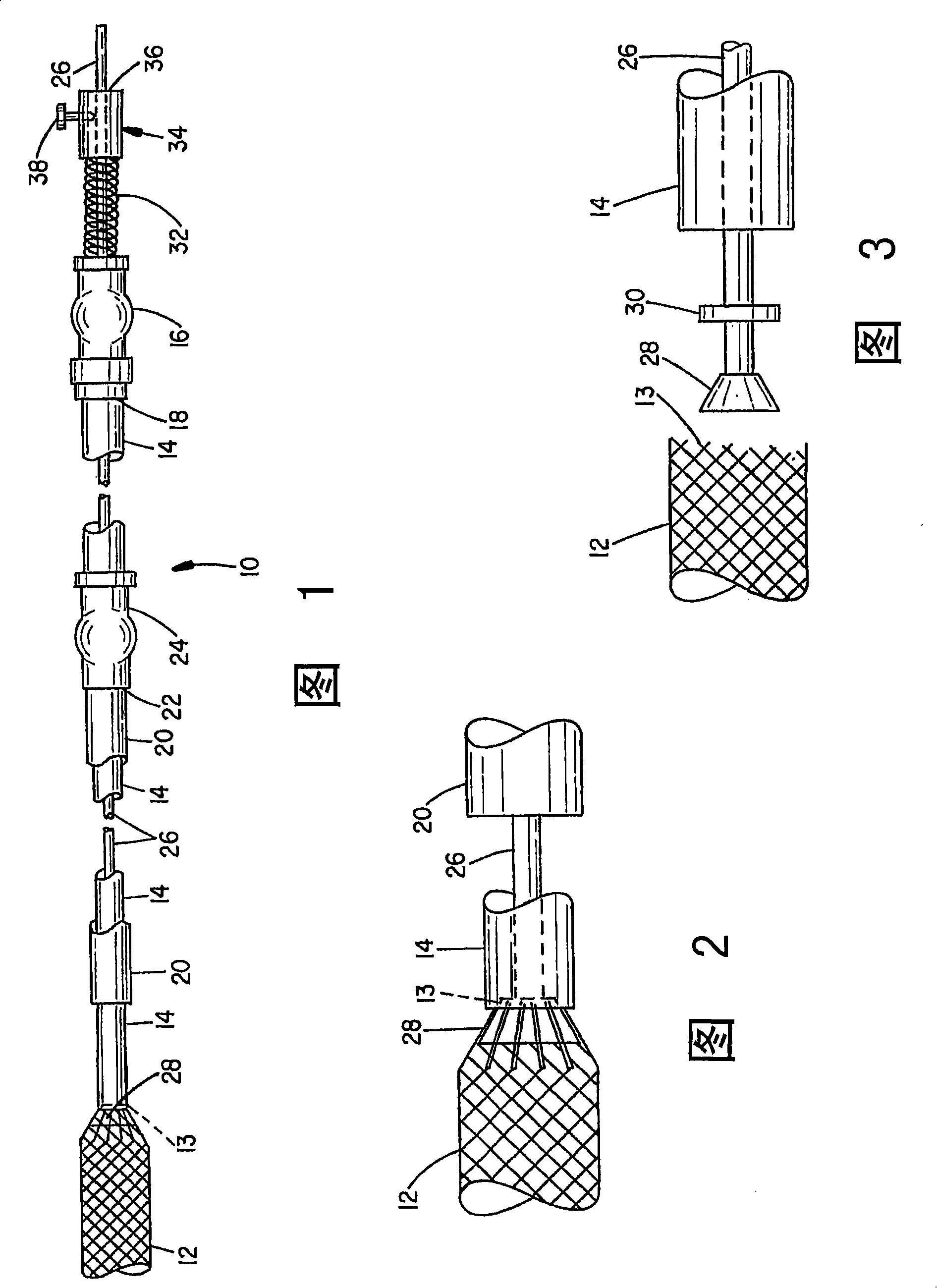
[0015] Referring initially to FIG. 1 , a percutaneous, transluminal stent or graft delivery system is indicated at 10 and, as described above, is used to deliver a stent or graft subject 12 to a target location within the vascular system, for example, to exclude arterial A stent or graft object 12 is delivered to the site of an abdominal aortic aneurysm to prevent further expansion and possible rupture of the aneurysm.

[0016] Vascular prosthesis 12 is preferably constructed of metal fabric in an expanded configuration and a collapsed configuration. When deflated, the prosthesis 12 can be configured to pass through the lumen of a catheter, and the graft can generally return to its expanded configuration when it is removed distal from the catheter at a target location in the patient's vasculature.

[0017] As described in U.S. Pat. No. 5,725,552 to Curtis Amplatz, the metal fabric comprising the prosthesis may comprise strands of braided metal wire, wherein the wire is prefera...


PUM


Abstract

The present invention provides a delivery mechanism for percutaneously routing a stent or graft through the vascular system and procedures for addressing an aneurysm or an otherwise damaged vessel. The delivery system includes an outer tubular guide catheter (20), an inner tubular delivery (pusher) catheter (14) coaxially disposed and slidable relative to the outer guide catheter and an elongated flexible wire or cable (26) that is coaxially insertable through the lumen of the inner tubular catheter and that has a frusto-conical bead affixed at the distal end thereof which is sized to at least partially fit within the lumen of the inner pusher catheter when a proximally directed tension force is applied between the elongated flexible wire or cable (26) with respect to the pusher catheter (14). By inserting a compressed coil spring between a proximal end portion of the pusher catheter (14) and the proximal end portion of the cable (26), the requisite clamping force is maintained to secure the stent or graft to the distal end of the pusher catheter until the compression spring force is removed. With the stent or graft clamped to the distal end of the inner pusher catheter, it can be drawn within the lumen of the outer guide catheter for delivery therewith to the target site.

Description

technical field [0001] The present invention relates generally to a percutaneous vascular procedure through the wall of a vessel lumen, and more particularly to a method for placing a stent, stent-graft, or tubular graft into a patient's vascular system at a desired target location of the conveyor. Background technique [0002] In the field of interventional cardiology, balloon angioplasty is currently the appropriate and common method for treating stenotic lesions in the vascular system to open partially blocked vessels and try to place a stent at the site of the treated lesion to prevent Restenosis. [0003] Stents useful in these methods must be able to assume a reduced-diameter configuration for delivery through a guide tube, but self-expand, or "balloon expand", upon exiting the distal end of the guide tube. [0004] In performing balloon angioplasty to place stents, the Seldinck technique is often used to access the vascular system and insert a tubular introducer wit...

Claims


Application Information

Patent Timeline
Patent Type & Authority Applications(China)
IPC IPC(8): A61F2/06
CPCA61F2/95
Inventor K·安普拉茨
Owner AGA MEDICAL CORP MS US
Why Eureka
Try Eureka