Ultrasonic machining spindle device

A technology for processing spindles and ultrasonic waves, which is applied in metal processing, metal processing equipment, metal processing machinery parts, etc., can solve the problems of speed limitation, inability to respond to high-speed rotation, wear or damage, etc., and achieve high reliability.

Inactive Publication Date: 2008-07-02
BOSCH CORP
View PDF1 Cites 26 Cited by
  • Summary
  • Abstract
  • Description
  • Claims
  • Application Information

AI Technical Summary

Problems solved by technology

[0004] However, in the conventional structure as above, since the slip ring is always in contact with the power supply brush, wear or damage is serious, therefore, stable and highly reliable processing cannot be ensured except that the power supply brush is frequently replaced. In addition to the problem, in order to reduce the wear or damage of the slip ring, the speed is also limited, and it cannot respond to the requirements of high-speed rotation.

Method used


Image

  • Ultrasonic machining spindle device
  • Ultrasonic machining spindle device
  • Ultrasonic machining spindle device

Examples


Embodiment Construction

[0026] Next, an embodiment of the present invention will be described with reference to FIGS. 1 to 3 .

[0027] In addition, members, arrangement|positioning, etc. which are demonstrated below do not limit this invention, Various changes are possible within the scope of the meaning of this invention.

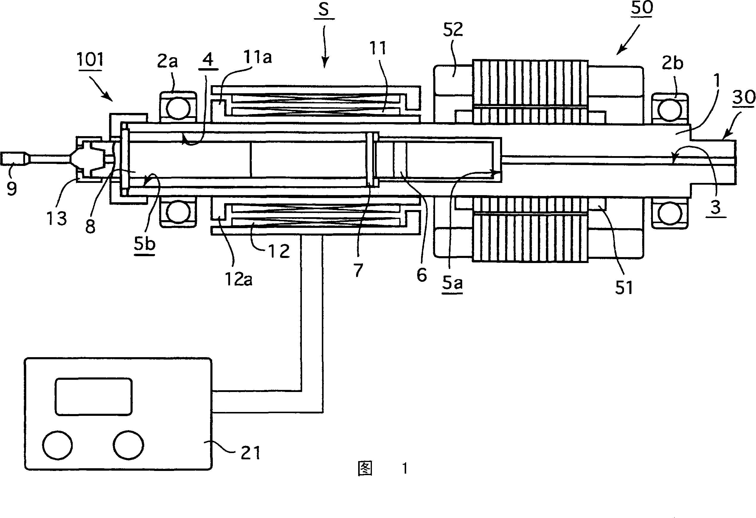
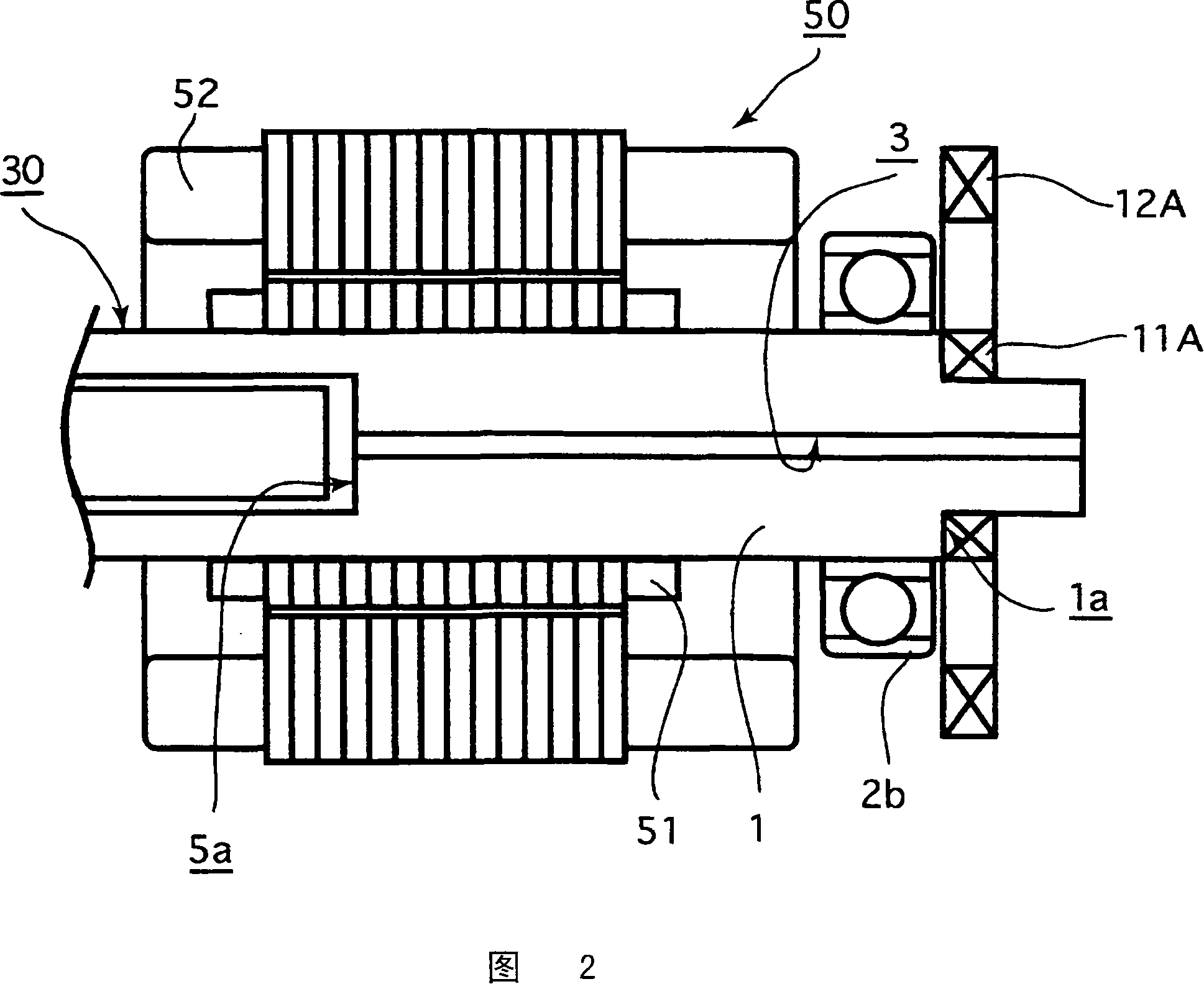
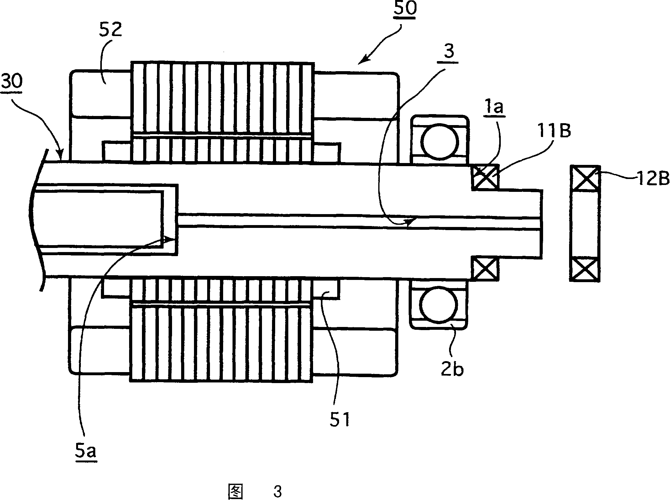
[0028] First, a configuration example of an ultrasonic machining spindle device in an embodiment of the present invention will be described with reference to FIG. 1 .

[0029] 1 shows in particular the structure of the processing spindle 101 and its vicinity, which becomes the main part of the ultrasonic processing spindle device S in the embodiment of the present invention. The processing spindle 101 has a shaft 30 rotatably supported by a bearing 2a or 2b and a The shaft 30 rotates a high-frequency motor 50, and the shaft 30 is provided with a vibrator 6 as an ultrasonic generating element, a horn 8, etc., which will be described later, and in addition, a tool grip for install...


PUM


Abstract

The invention does not cause wear or damage of parts, and also does not require regular replacement of parts, and can provide stable electrical signals to ultrasonic generating elements. On the outer peripheral surface of the housing (1) constituting the shaft (30) of the machining spindle (101), the receiving coil (11) connected to the vibrator (6) is wound and assembled, on the other hand, around it, spaced Appropriate intervals are provided with sending coils (12) coaxially, and the predetermined electrical signals output from the ultrasonic drive device (21) for driving the vibrator (6) are applied to the sending coils (12), which can A predetermined electrical signal is applied to the vibrator (6) through the electromagnetic induction between the sending coil (12) and the receiving coil (11) and through the receiving coil (11).

Description

technical field [0001] The present invention relates to an ultrasonic machining spindle device, and more particularly, to an ultrasonic machining spindle device that achieves improved reliability of power supply to ultrasonic generating elements, simplified structure, and the like. Background technique [0002] In recent years, machine tools using a machining method called ultrasonic milling, which performs machining operations while applying ultrasonic vibrations to the axial direction of the tool, have been proposed in various ways (such as , refer to Patent Document 1, etc.). [0003] In an apparatus for performing such ultrasonic milling, an element for generating ultrasonic waves is generally installed near a rotating tool and rotates together with the tool. And, the most common structure of this ultrasonic generating element is: the provision of electric signal is required, and when this electric signal is provided, slip ring (slip ring) is installed on the shaft that...

Claims


Application Information

Patent Timeline
Patent Type & Authority Applications(China)
IPC IPC(8): B23B19/02B23B37/00B06B1/02
CPCB23B29/125B23B37/00B23B2270/10B23Q2230/004B06B1/02
Inventor 久保田治由井隆行古川英雄
Owner BOSCH CORP
Why Eureka
Try Eureka