Motor and its control device

A technology of electric motors and electrical angles, which is applied in the direction of electromechanical devices, electric components, synchronous motors with stationary armatures and rotating magnets, etc., and can solve the problems of reduced productivity of windings, complex structures, and difficulties in miniaturization of motors

Inactive Publication Date: 2008-07-02
DENSO CORP
View PDF5 Cites 4 Cited by
  • Summary
  • Abstract
  • Description
  • Claims
  • Application Information

AI Technical Summary

Problems solved by technology

[0005] However, the conventional brushless motors disclosed in Fig. 141, Fig. 142, Fig. 144 and Patent Document 1 have the following problems: since the motor winding needs to be wound according to each stator magnetic pole, the structure is complicated; on the inner side, so the productivity decreases due to the winding of the motor winding
In addition, this structure also has the problem that it is difficult to achieve miniaturization, high efficiency, and low cost.
In addition, since there are only three salient poles of the stator in the electrical angle range of 360 degrees, there is a problem that it is difficult to gener

Method used


Image

  • Motor and its control device
  • Motor and its control device
  • Motor and its control device

Examples


Embodiment Construction

[0192] Next, a motor to which an embodiment of the present invention is applied will be described in detail with reference to the drawings.

[0193] First, the conventionally known basic structure of the electric motor of the present invention will be described, and then the structure providing the characteristic features of the present invention will be described.

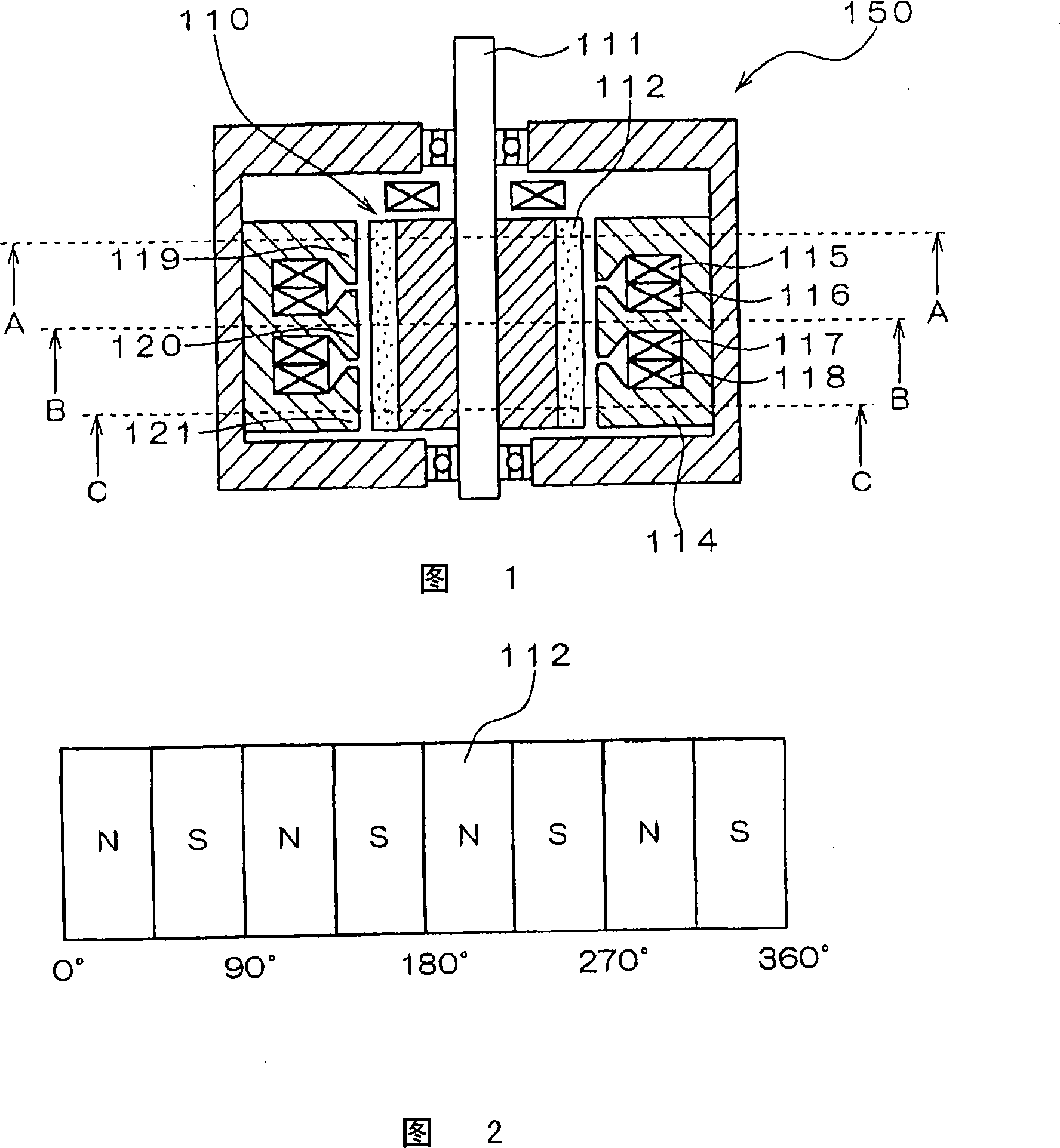
[0194] FIG. 1 is a cross-sectional view showing a basic structure of a brushless motor as a motor of this embodiment. The brushless motor 150 shown in FIG. 1 is an 8-pole motor that operates in 3-phase AC, and includes a rotor shaft 111 , permanent magnets 112 , and a stator 114 .

[0195] The rotor 110 has a plurality of permanent magnets 112 arranged on the surface. These permanent magnets 112 are alternately arranged with N poles and S poles in the circumferential direction along the surface of the rotor 110 . FIG. 2 is a developed view of the rotor 110 in the circumferential direction. The horizontal axis r...


PUM


Abstract

A motor (100) includes: a rotor (10) having permanent magnets (12) with N poles and S poles alternately arranged in the circumferential direction; seven stator magnetic pole groups, each having a plurality of stator magnetic poles (53, 54, 55, 56, 57, 58, 59) arranged in the circumferential direction in such a manner that the stator magnetic poles are shifted both in the circumferential directionand the axial direction; and a plurality of loop windings (41, 42, 43, 44, 45, 46, 47, 48, 49, 50, 51, 52) formed in the circumferential direction while being arranged at the adjacent position to each of the stator magnetic pole groups along the axial direction.

Description

technical field [0001] The present invention relates to an electric motor mounted on an automobile, a truck, etc., and a control device thereof. Background technique [0002] Conventionally, there is known a brushless motor in which coils of respective phases are concentratedly wound around stator poles (for example, refer to Patent Document 1). Fig. 141 is a longitudinal sectional view showing a schematic structure of such a conventional brushless motor. In addition, FIG. 143 is a cross-sectional view along line A1-A1 in FIG. 141 . These figures show a 4-pole, 6-slot brushless motor. The winding structure of the stator is so-called concentrated winding, and the coils of each phase are concentratedly wound on each stator magnetic pole. In addition, FIG. 142 shows the arrangement relationship of windings such as U, V, W, etc. in a state where the stator is developed one turn in the circumferential direction. The horizontal axis is expressed in electrical degrees, and one r...

Claims


Application Information

Patent Timeline
IPC IPC(8): H02K21/14
CPCH02K21/145H02K3/28H02K21/24H02K1/2766H02K21/16H02K1/246H02K1/2773H02K1/145H02K21/227H02K21/14
Inventor 梨木政行
Owner DENSO CORP
Why Eureka
Try Eureka